Technical Articles
Why Precast Column Grout Sleeves Fail Ultrasonic Testing: The Void Behind the Vent Port
Incomplete grouting in precast column and shear wall rebar splice sleeves threatens structural development length. Diagnose air voids, bleed water segregation, and verify bottom-up pumping controls before structural sign-off.
On an assembling multi-storey precast job site, column and shear wall erection appears deceptively straightforward. A mobile crane lowers a 6-tonne precast column onto leveling shims, lowering protruding dowels into matching cast-in metallic grout sleeves. The perimeter bedding mortar is packed, and a grouting crew pumps cementitious mortar into the lower injection port until grey paste spills from the upper vent. The ports are plugged, the crane unhooks, and the team moves to the next grid line.
Days later, an independent testing agency conducts non-destructive testing (NDT) using ultrasonic pulse-echo or impact-echo methods. In 10% to 25% of the sleeves, acoustic reflections return an immediate anomaly: *a severe acoustic impedance mismatch in the upper 40 mm to 80 mm of the sleeve*. The grout has failed to fully encapsulate the upper anchorage deformation ribs of the rebar. The development length required by ACI 318, Eurocode 2 (EN 1992-1-1), or fib Bulletin 102 is compromised, threatening structural load transfer under seismic or wind moments.
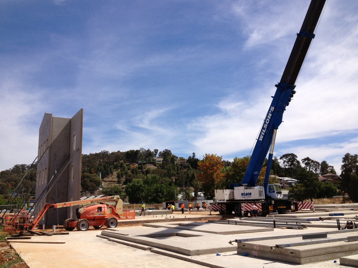

The illusion of the overflow port: Why full ports hide empty sleeves
The primary psychological trap on site is assuming that when grout flows out of the upper observation port, the sleeve interior is completely dense. In reality, grout flow through an eccentric annular chamber—interrupted by deformation ribs, an internal centering stop, and the deformed rebar—is highly susceptible to laminar channeling and air trapping.
If the crew pumps too rapidly or introduces pressure surges, grout channels upward along the path of least resistance (typically along the smooth outer sleeve wall), exiting the overflow port while leaving a pocket of trapped air compressed against the opposite shoulder or top dead-end of the coupler. Once pumping ceases and the port is plugged, the compressed air pocket expands, pushing the fresh paste down and establishing a permanent void.
The three physical root causes of internal sleeve voids
- 1. The Fatal Top-Down Pumping Mistake:* On sites lacking specialized progressive-cavity or peristaltic grout pumps, untrained workers sometimes pour or inject grout into the upper vent port, assuming gravity will settle the paste. Air cannot escape downward through the viscous grout matrix; it is driven upward and trapped in the top anchorage zone.
- 2. Water Overdosage and Bleed Water Lenses:* Factory-bagged non-shrink sleeve grouts are formulated with ultra-fine cement, silica fume, and high-range polycarboxylate superplasticizers requiring tight water-powder ratios (typically 0.12 to 0.14 by weight). When site workers add extra water to make pumping 'easier', excess water segregates under hydrostatic pressure. A bleed water lens collects at the highest elevation of the sleeve. As hydration progresses, this water evaporates or reabsorbs into the porous paste, leaving behind a dry void precisely where mechanical anchorage is most critical.
- 3. Premature Vent Port Capping:* When pumping from the bottom inlet, the first fluid emerging from the upper vent is often a froth of air bubbles, wash water, and diluted paste. If the nozzle operator caps the vent the instant any fluid appears, this low-density slurry remains trapped inside. Pumping must continue until pure, dense, air-free grout flows in a continuous stream before inserting the rubber sealing plug under positive pressure.
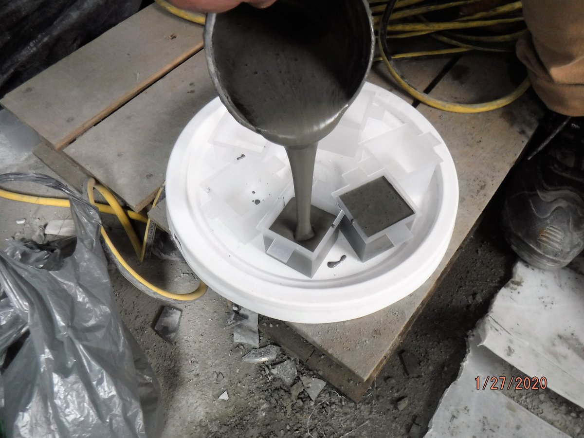

Non-destructive testing and verification methods
Because grouted sleeves are embedded within dense precast concrete elements, visual inspection is impossible once the formwork is stripped. Structural engineers and building authorities enforce three primary verification tiers:
- Ultrasonic Guided Wave & Pulse-Echo Testing:* Transducers mounted on the protruding dowel or the precast concrete face emit high-frequency acoustic waves. The wave velocity through a solidly grouted sleeve is distinct from that of an air-filled steel-air interface. A significant reflection peak at the upper anchorage boundary confirms a void.
- Impact-Echo (IE) Resonance Frequency:* Mechanical impact on the element surface excites stress waves. Resonance shifts reveal delaminations and voided sleeve cavities behind the cover concrete without destructive drilling.
- Drill Borescope / Industrial Endoscope Verification:* When acoustic NDT detects a suspected void, an 8 mm diamond core hole is drilled directly through the precast column face into the top vent channel. An illuminated flexible borescope probe is inserted to visually photograph the void depth, measure the exposed rebar length, and verify the physical condition of the grout surface.
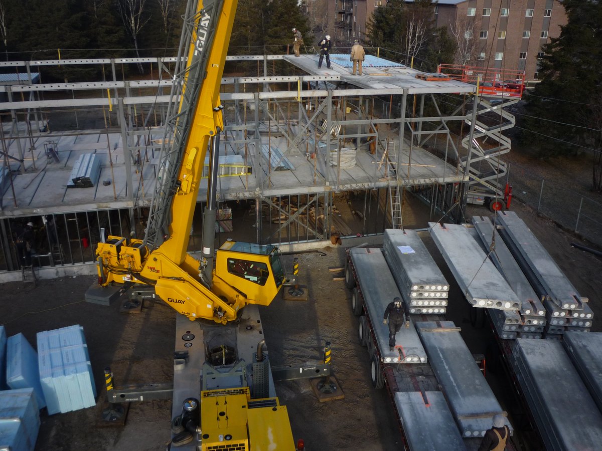

The five on-site quality gates for zero-void sleeve grouting
To prevent void formation and pass third-party testing on the first attempt, general contractors and precasters must enforce five strict hold points during the grouting shift:
- 1. Flow Cone Fluidity Verification (ASTM C939 / EN 445):* Every batch of grout must pass a flow cone test immediately after high-shear mechanical mixing. The standard efflux time must measure strictly between 10 and 15 seconds. If the grout fails the flow test, discard the batch; never adjust by adding uncalibrated water in the field.
- 2. Mandatory Bottom-Up Continuous Pumping:* Grout must always be injected into the lowest inlet port using a steady progressive-cavity pump under 0.2 to 0.4 MPa working pressure. Gravity pouring or top-filling must be contractually prohibited.
- 3. Sustained Overflow Purge:* Allow at least 200 ml of pure, bubble-free grout to discharge from the upper vent into a waste bucket. Only when the discharge matches the density and consistency of the intake grout may the vent be plugged.
- 4. Positive-Pressure Plug Sequence:* Insert and lock the upper vent plug first while maintaining pump pressure. Hold the pressure for 5 seconds to consolidate the matrix against the upper sleeve shoulder, then seal the lower inlet port before releasing nozzle pressure.
- 5. Daily Compressive Strength Sampling (EN 196-1 / ASTM C109):* Cast at least six 40x40x160 mm prisms or 50 mm cubes per shift. The specification must verify early compressive strength (≥35 MPa at 24 hours, ≥85 MPa at 28 days) and non-shrink expansion (0.02% to 2% within 3 hours).
Remediation: What to do when a sleeve fails inspection
If an endoscope or ultrasonic survey confirms an anchorage void exceeding 20 mm in depth, structural sign-off must be withheld until engineer-approved remediation is completed. The standard repair involves drilling two micro-ports (6 mm to 8 mm) into the top and bottom of the voided cavity, vacuum-purging all dust, and injecting a low-viscosity, structural epoxy resin or ultra-fine micro-cement under low pressure (0.1–0.2 MPa) until dense resin fills the vent. Once cured, the repaired sleeve must be re-tested non-destructively to confirm 100% solid acoustic transmission.
In precast industrial construction, the integrity of a connection is never settled by looking at a sealed plastic plug. By controlling the mix rheology, respecting bottom-up fluid dynamics, and verifying every shift with rigorous NDT hold points, engineering teams ensure that their precast buildings perform with the full seismic resilience designed on the drawing board.