Technical Articles
A Waterfront Is Not One Structure: How Precast Systems Work Together
A convincing waterfront design begins below the finished edge: with the ground that supports it, the water that acts on it and the connections that make separate concrete elements behave as a system.
From a promenade, a waterfront can look reassuringly simple: a line of concrete, a planted bank, a deck above the water. The structural arrangement is rarely so simple. Behind that continuous edge are different load paths, different responses to water and different construction sequences. A wall must retain soil. A foundation must carry load into the ground. A revetment protects an exposed surface. A channel controls the route of water. None of these duties disappears because the components share a material or a manufacturer.
Precast construction makes the distinction particularly important. The units arrive with their geometry already fixed; many of the critical decisions concern what happens between them, beneath them and during installation. A well-made element cannot compensate for a support condition or joint that the design has left unresolved.
Read the section before choosing the element
The useful starting drawing is not the waterfront elevation but the section through the land and water. It should explain what is being supported, what is being retained and where the forces go. Ground strata, retained levels and water conditions then give that section meaning. Without them, selecting a pile or wall profile amounts to choosing a solution before defining its task.
A riverfront walkway beside a planted bank illustrates the problem. Its deck loads need a route through beams, caps and foundations. The retaining structure has a separate duty to resist the actions associated with the bank. The planted surface has another: protection against erosion under its design conditions. These systems meet, but they are not interchangeable. Their interfaces deserve at least as much attention as the visible finish.
Construction adds a second set of sections to consider. The final arrangement may be clear while the route to it is not. Driving, lifting, positioning, filling and grouting each impose practical constraints. The question is not only whether the completed structure works, but how it reaches that condition without relying on a connection or support that has not yet been completed.
Pile selection is a question of load path and installation
PHC, PRC and SC pile families offer different structural arrangements. The presentation associates PHC piles with foundation applications, describes PRC piles in terms of mixed reinforcement, and identifies SC piles as steel–concrete composite members. Those distinctions are useful, but the acronym is only the beginning of a specification.
The governing demand may involve axial load, lateral action, bending, shear or a combination. The delivered section, reinforcement and splice must answer that demand together. A proposal that describes the pile shaft in detail but leaves its splice unresolved has not yet described a continuous load path.
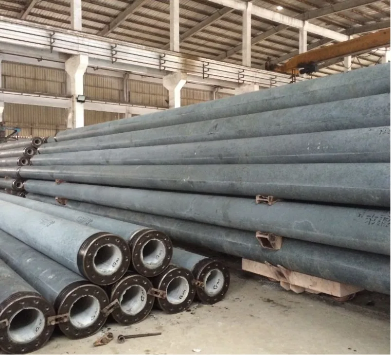
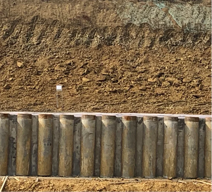
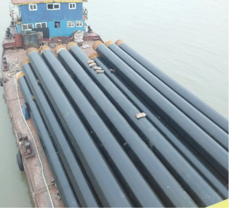
The photographs move from stored hollow sections to a bank-side installation and steel-cased units. They make the range tangible; they do not establish which arrangement suits a particular ground profile. That judgement also depends on installation. The supplied technical material explicitly includes driving, cracking and splice checks, alongside the completed member’s structural duties.
Exposure further changes the comparison. For a steel-cased proposal, coating and corrosion allowance belong with the connection details, not in a separate architectural finish schedule. For concrete members, cracking and the specified exposure conditions must be considered with the structural arrangement. There is no useful universal ranking of these families: the better proposal is the one whose section, joints, installation method and exposure provisions form a consistent answer to the site.
A bank wall must work below the waterline
Wave-section bank piles, hollow PC wall piles and U or straight sheet-pile forms create different geometries along an edge. Their engineering significance lies in the complete wall: embedded portion, connections, alignment and interaction with the retained ground and water.
The finished landscaped bank below shows how little of that system may remain visible. Its appearance tells us something about the public realm, but nothing dependable about embedded depth or joint treatment. The stored hollow units reveal the section more clearly, yet still leave the installed joints and grouting to be resolved.
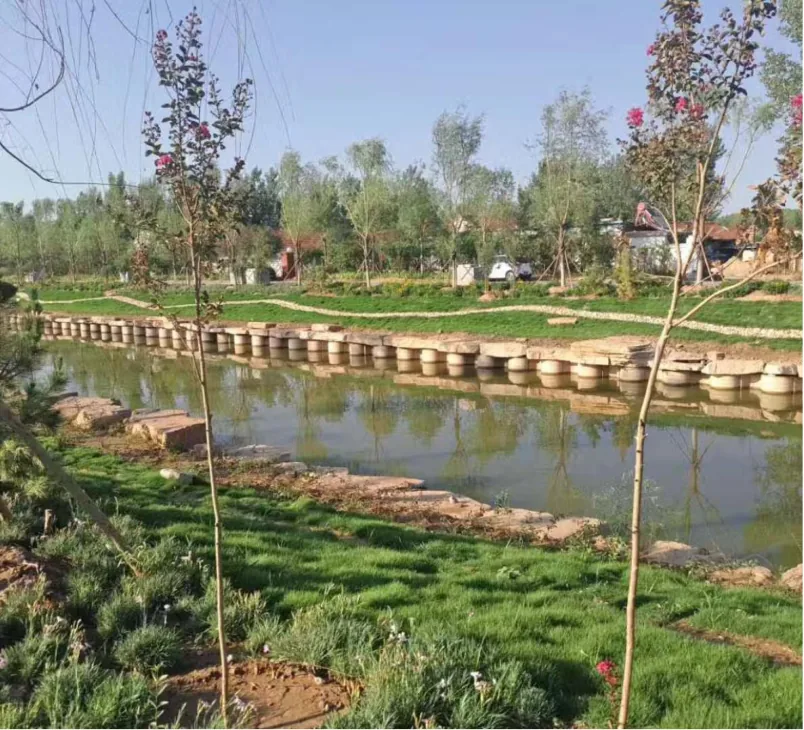
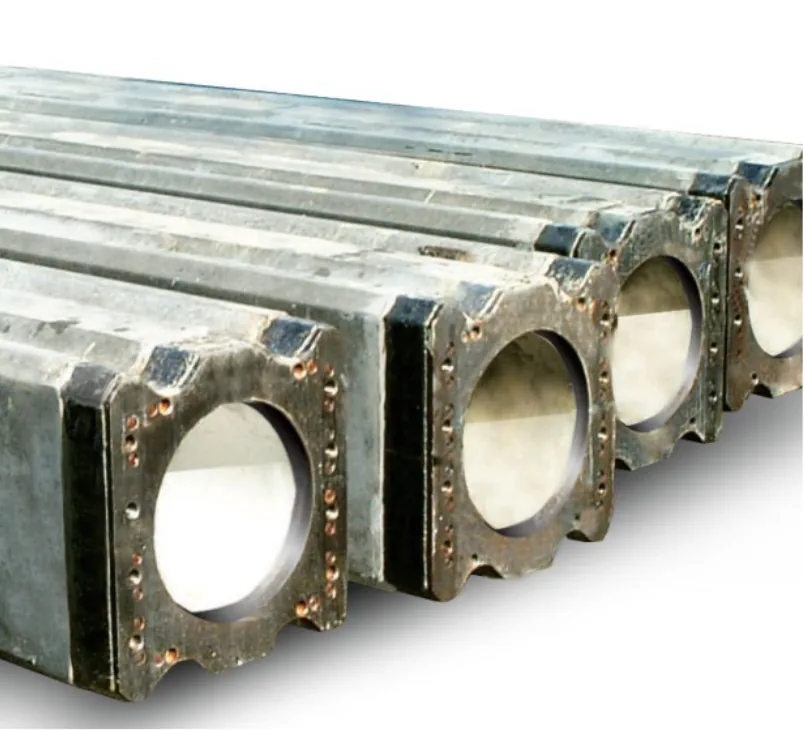
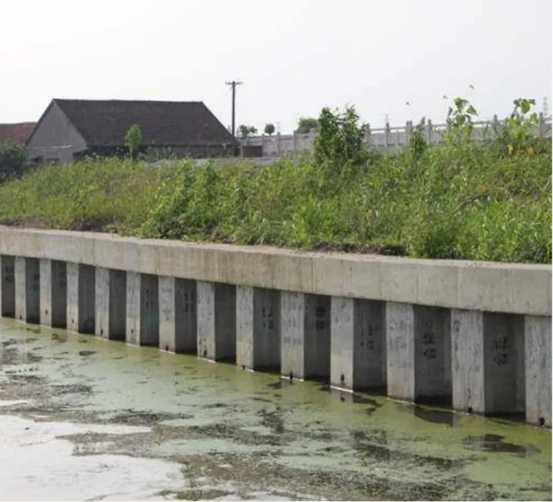
This is where structural and hydraulic detailing meet. Interlocks and joints need a defined role; seepage and drainage cannot be treated as the same problem as bending resistance. Similarly, choosing a deeper-looking profile in an elevation does not establish an adequate embedded toe. The source material treats stability, bending, water control and installation alignment as connected checks, rather than benefits inherent in a particular shape.
A planted slope requires a different reading. Ecological blocks can form a protective surface while accommodating vegetation. They do not turn an unstable bank into a stable one merely by covering it.
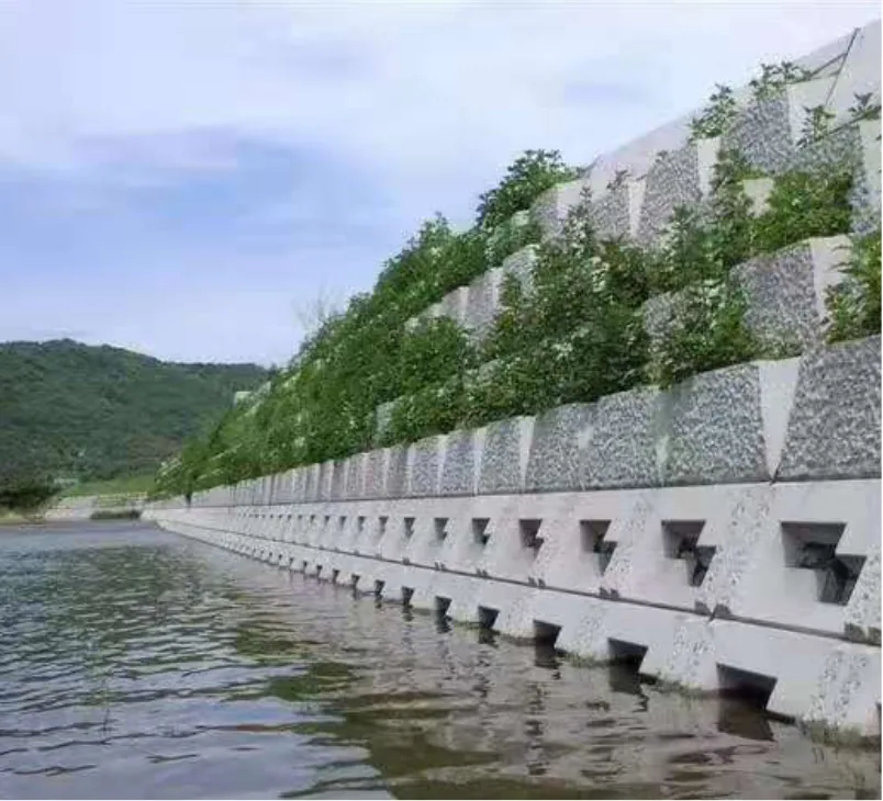
The design must distinguish surface erosion from movement of the slope as a whole. Scour, filters and drainage remain part of the protective arrangement; overall slope stability remains a ground-engineering question. The choice between a vertical retaining edge and a sloping, planted treatment is therefore more than a visual preference. It changes the geometry and the functions that the system must perform, and those functions must still be accounted for.
The retaining wall includes what is placed around it
L-shaped units and gravity-box units are easy to understand as precast objects. They are less useful when assessed as objects alone. Their structural behaviour depends on the completed assembly and its relationship with the foundation and retained material.
For the L-wall arrangement, sliding, overturning, bearing and backfill are explicit design considerations. For the gravity-box arrangement, fill, drainage, keys and foundations are integral to the technical description. These are not incidental site works to be decided after the concrete order.
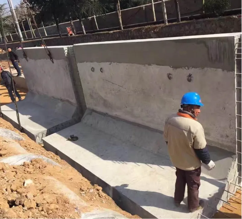
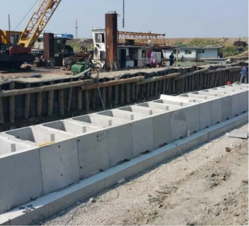
The distinction becomes acute during construction. A placed unit is not necessarily the completed retaining system: filling, backfilling, drainage and adjoining work may remain outstanding. The erection sequence should identify what gives the arrangement its intended support at each stage, rather than assuming that the final condition already exists.
This also exposes a common boundary in procurement. One party supplies the shell; another prepares the base and places fill. Unless a coordinated detail links those scopes, each may be executed as specified while the assembly remains inadequately defined. The most valuable drawing is often the one that crosses that contractual boundary.
Connections decide whether the assembly works
On a boardwalk, the deck receives attention because it is what users see. Structurally, it is one link in the pile–cap–beam–deck chain. The connection between each link must carry the action assigned to it, and the construction method must make that connection achievable and inspectable.
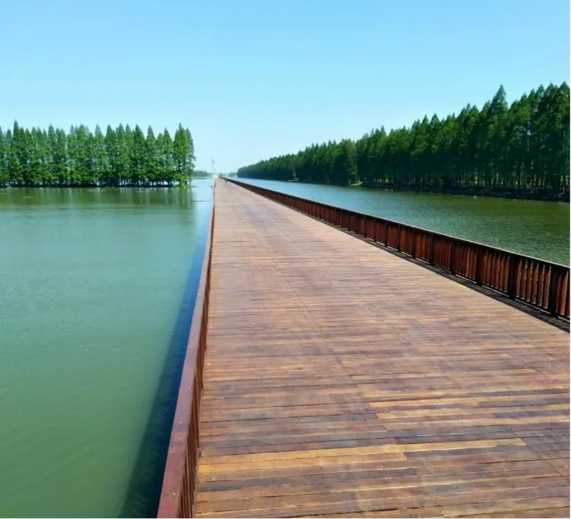
The waterfront photograph illustrates the setting rather than establishing the material of every visible finish. The accompanying technical sequence is more revealing: joint type, reinforcement continuity, grouting and inspection must be settled alongside deck, railing and live-load requirements. Choosing an assembly route before resolving those details reverses the engineering logic.
Inspection is particularly important at interfaces that become concealed. If a connection relies on grout or reinforcement continuity, the design and work sequence should state what is to be checked before subsequent construction closes access. A detail that can be drawn but cannot be reliably executed or inspected is not a satisfactory resolution.
The same principle separates a ground-supported channel from an elevated aqueduct. Both convey water, but their support and movement conditions differ.
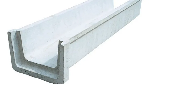
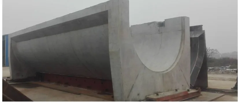
For the channel, bedding, gradient and joint sealing connect the individual units into the intended watercourse. For the aqueduct, span supports, movement provisions and erection sequence add another structural layer. A similar water-carrying cross-section does not imply a similar support design.
Here, the joints must be considered in relation to both structure and conveyance. Their intended movement and sealing functions need to agree with the supports and construction tolerances. Line and level, lifting arrangements and access for completing the joints belong in the same discussion—not in separate documents that never meet.
The coastal edge cannot borrow a sheltered-bank detail
Coastal armor introduces a different water-action problem. Wave conditions, toe scour, placement and durability govern the assessment in a way that cannot be resolved by extending a canal-bank detail toward the sea.
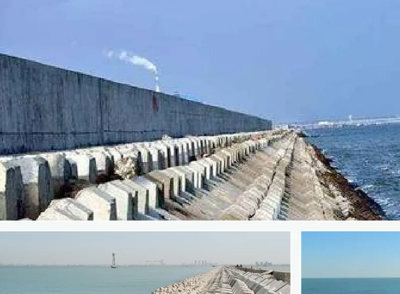
The image conveys the idea of a protected shoreline, but the engineering decision concerns the whole protective arrangement. Unit form alone does not determine the required size or placement for another coast. Nor can attention to the exposed armor replace consideration of the toe and the conditions supporting the protection.
For a project team, the essential distinction is between identifying a possible system and establishing its suitability. The first can begin with a photograph. The second requires the site’s water conditions and a coordinated design. Transferring a detail without transferring—and checking—its assumptions is not standardization; it is a change of engineering problem left unexamined.
Standardize the elements, resolve the interfaces
The strongest case for precast is not that one family of units can solve every waterfront problem. It is that defined elements can be brought into a clearly designed assembly. That requires agreement on three things before manufacture: what each element does, how its actions reach the ground, and how the intended connections are achieved on site.
A useful design review should therefore follow the load path through the section, then follow the construction sequence through the joints. Where the two accounts disagree—an assumed support not yet present, a joint without an inspection route, a drainage detail omitted between packages—the project still has work to do.
The finished edge may read as one continuous place. Its reliability depends on respecting the different structures behind that appearance. Standardization is most useful when it makes those responsibilities clearer, not when it conceals them behind a familiar concrete shape.