Troubleshooting
Circular Concrete Utility Poles: Inspection, Measurement and Load Testing
A current-standard technical reference for finished-pole identity, appearance inspection, dimensional measurement, mechanical testing and test evidence.
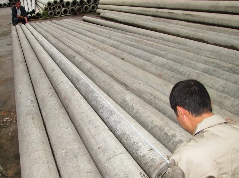
Technical summary
Finished circular concrete poles are inspected as identified products, not anonymous concrete tubes. A defensible record links the current adopted product standard to product marking, appearance, measured geometry, reinforcement details, the correct mechanical-test arrangement, staged readings, observed failure behavior and release disposition. GB/T 4623-2025 is the current Chinese national product standard from 1 May 2026 and fully replaces the 2014 edition.
Field notes
Circular Concrete Utility Poles: Inspection, Measurement and Load Testing operating variables
Finished circular concrete poles are inspected as identified products, not anonymous concrete tubes. A defensible record links the current adopted product standard to product marking, appearance, measured geometry, reinforcement details, the correct mechanical-test arrangement, staged readings, observed failure behavior and release disposition. GB/T 4623-2025 is the current Chinese national product standard from 1 May 2026 and fully replaces the 2014 edition.
Parameters to verify
- Identify pole type, geometry, strength designation and governing standard before inspecting results.
- Separate routine release evidence from type-inspection or mechanical-test evidence.
- Record measuring position, instrument, orientation and specimen identity with every result.
- Read crack development, deflection and residual response against the current adopted test procedure.
Records and inputs
- Product designation and drawings
- Adopted standard and inspection plan
- Calibrated measurement records
- Mechanical-test setup and raw data
Failure modes to watch
- Edition control is missing.
- Specimen identity cannot be traced.
- Measurement position or instrument is unclear.
Visual workflow
From identified finished pole to traceable mechanical-test record
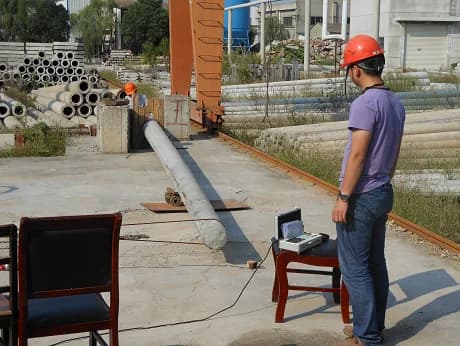
The photograph shows the structural test arrangement; the technical record must also preserve product identity, fixture geometry, loading stages, measurements and observed behavior.
Fix designation, drawing, standard edition, batch and specimen number.
Map appearance before transport, fixtures or loading change the surface.
Record dimensions, cover and interfaces at defined stations.
Set root restraint, loading point, direction and instruments.
Preserve every stage, deflection reading and crack observation.
Reconcile raw data, calculations, photographs and disposition.
Production context
Circular concrete utility-pole inspection connects the declared product class to visible condition, measured geometry, reinforcement details, mechanical response and a traceable release record.
Field sequence
Technical method and evidence chain
Read each stage with the product definition, adopted standard, approved procedure and item-specific records.
1. Fix product identity before reading a result
The inspection file should first identify the pole by designation, nominal length, tip and butt geometry, reinforcement or prestressing type, mechanical class, production batch and adopted standard. The product drawing and marking system must use the same identity as the inspection report.
A measured diameter or a load value has little technical meaning when the tested specimen cannot be linked to the declared product. Record the pole marking, specimen number, production date and inspection status before measurements begin.
- Photograph the product marking and the full specimen before testing.
- Record the standard number and edition, not only the standard title.
- Keep the drawing revision and inspection-plan revision with the report.
2. Separate release inspection from extended verification
Appearance and dimensional checks, mechanical tests and other product evidence do not necessarily occur at the same frequency or on the same specimen. The adopted standard and the approved inspection plan define the inspection route, sample selection, retest rules and disposition.
The report should state why each specimen was selected and whether the work is routine release, periodic verification, type inspection, a project witness test or an investigation. This prevents an isolated test from being presented as evidence for a scope it did not cover.
3. Appearance inspection is a mapped condition record
Typical observations include surface cracks, joint leakage traces, exposed reinforcement, honeycombing, local concrete loss, rough or adhered surface material, internal-wall defects and damage at end rings or fittings. The defect name alone is not enough.
Record position along the pole, circumferential orientation, length or area, measured width or depth where required, nearby reinforcement or fitting, photograph scale and disposition. Internal-wall inspection needs adequate lighting and a view that preserves orientation.
- Use an overview image to locate the observation and a close image with scale to characterize it.
- Distinguish production defects from handling or test-induced damage.
- Keep repair, rejection or engineering disposition linked to the original observation.
4. Dimensional inspection needs defined stations and orientation
Length, outside diameter, wall thickness, straightness or curvature, end inclination and the location of holes or fittings are different measurements with different reference surfaces. Each result should state the measuring station, orientation, instrument and calculation method.
Wall thickness should be read at defined positions around the section rather than represented by one convenient point. Outside diameter and end inclination should be measured without using damaged edges or surface deposits as the reference. Straightness measurements require a documented datum and support condition.
5. Reinforcement cover and embedded interfaces remain product evidence
Cover measurement, exposed steel, prestressing-steel position, end rings, reserved holes and embedded fittings affect durability, handling and structural interfaces. The method should match the geometry and material system, and the instrument should be appropriate for the expected cover range.
Where a local opening or fitting interrupts the regular section, record the detail against the drawing rather than treating it as a generic surface condition. Destructive confirmation, when required, should remain traceable to the same specimen and location as the non-destructive reading.
6. The mechanical-test arrangement must reproduce the defined structural model
A pole test arrangement establishes root restraint, span or lever geometry, loading point, load direction and measurement stations. Tapered and cylindrical pole arrangements can require different restraint details; the fixture cannot be inferred from a photograph of another pole type.
Before loading, verify specimen orientation, root seating, fixture contact, distances, loading cable or actuator alignment, load measurement, deflection devices and crack-observation positions. Photograph the full arrangement and the critical restraint and loading interfaces.
- Record calibrated instrument identities and measurement resolution.
- Check that the applied force direction does not introduce an unintended torsional component.
- Preserve actual fixture dimensions and specimen support conditions in the test record.
7. Preserve the loading history, not only the endpoint
The useful record connects each loading stage to time, applied load, deflection, crack initiation and development, unloading or residual response where required, and the final observed condition. Photographs should be timestamped or otherwise linked to the corresponding loading stage.
Cracking, concrete crushing, reinforcement exposure, local failure near the root or a fixture-related anomaly describe different events. The report should separate specimen behavior from test-setup effects and retain raw readings before calculation or rounding.
8. Close the file with edition control and disposition
The final evidence package should include product identity, drawings, adopted standards, inspection plan, calibration status, appearance map, dimensional data, test setup, raw readings, calculations, photographs, deviations and authorized disposition.
The 2016 source training deck used for the field photographs was organized around GB/T 4623-2014. That edition is now superseded. Its photographs remain valid records of inspection subjects, while current acceptance values and test requirements must be taken from GB/T 4623-2025 and other currently adopted documents.
Field photographs
What the record should show
Each image is tied to a specific production, test or acceptance interface; none is a generic placeholder.
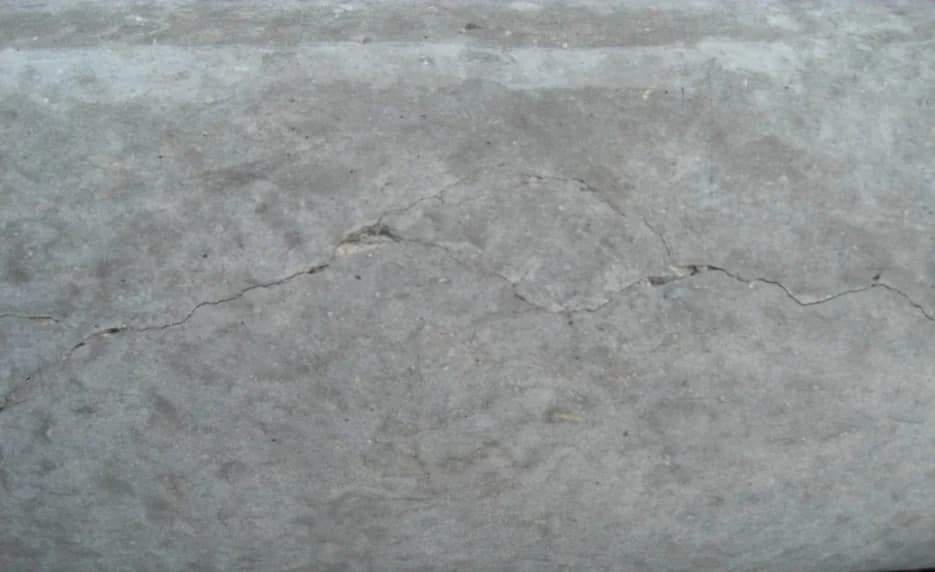
A close image records crack pattern, while the inspection sheet must add pole identity, location, orientation, scale and disposition.
Do not classify a defect from an unscaled close-up alone.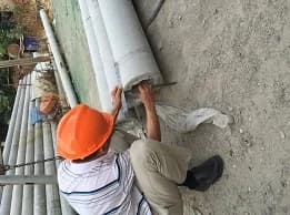
Wall thickness is a finished-product measurement taken at defined section positions.
Record the station, circumferential position, instrument and individual readings.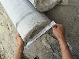
End geometry is checked against a documented reference plane rather than judged visually.
Damaged edges and surface deposits should not become the measurement datum.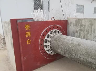
The root fixture is part of the mechanical model and must match the prescribed arrangement for the specimen type.
Record seating, contact, fixture geometry and any movement during the test.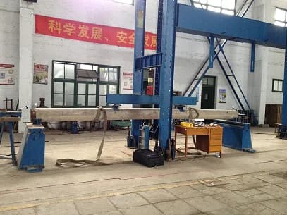
A complete setup view preserves the relationship between restraint, loading point and measurement stations.
Detailed close-ups should supplement, not replace, the full arrangement photograph.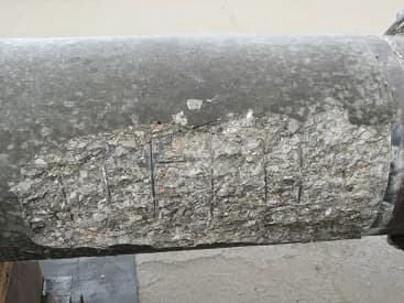
Post-test damage is interpreted with the loading history, crack observations and setup records.
Separate specimen failure behavior from accidental fixture or handling damage.Where this applies
- Reinforced and prestressed circular concrete poles for power distribution and transmission applications
- Circular poles used for communications, lighting, signals, monitoring and other utility structures where the adopted product standard permits
- Factory release, periodic verification, type inspection and third-party product-quality review
- Technical review of pole markings, finished dimensions, appearance, reinforcement interfaces and mechanical-test records
Engineering variables
- Identify pole type, geometry, strength designation and governing standard before inspecting results.
- Separate routine release evidence from type-inspection or mechanical-test evidence.
- Record measuring position, instrument, orientation and specimen identity with every result.
- Read crack development, deflection and residual response against the current adopted test procedure.
System interfaces
- Reconcile product markings, drawings, inspection records and test specimen identity.
- Read appearance, dimensions, reinforcement cover and mechanical behavior as connected evidence sets.
- Keep raw readings, loading stages, photographs and final observations together instead of reducing the test to pass or fail.
Production evidence checklist
| Production variable | Why it matters in production | Records or evidence to inspect | Interface risk |
|---|---|---|---|
| Product identity | Connects the tested pole to its declared geometry, reinforcement system, class and production batch. | Marking photograph, drawing, product designation, batch record and specimen number. | Results cannot be assigned reliably when the specimen identity or drawing revision is missing. |
| Appearance map | Records visible and internal-wall conditions before handling or testing changes the specimen. | Overview and scaled close photographs, location, orientation, dimensions and disposition. | An isolated close-up cannot distinguish production, handling and test-induced damage. |
| Finished dimensions | Confirms released geometry independently from steel-mold settings. | Defined stations, orientations, calibrated instruments, raw readings and calculations. | One convenient reading can hide circumferential or longitudinal variation. |
| Reinforcement interfaces | Documents cover, steel position, end rings, holes and embedded fittings that affect durability and connection details. | Cover readings, detail photographs, drawing references and destructive confirmation where specified. | A local fitting or opening may invalidate a generic measurement assumption. |
| Test arrangement | Creates the root restraint, load path and measurement geometry required by the adopted method. | Full setup photograph, fixture dimensions, support condition, loading point and instrument locations. | An incorrect restraint or force direction changes the structural model being tested. |
| Loading history | Connects applied load to deflection, cracking, unloading response and observed failure. | Timestamped raw readings, observation sheets, staged photographs and calculation record. | The endpoint alone cannot show when or how the response developed. |
| Edition and disposition | Shows which current requirements controlled the inspection and how deviations were resolved. | Standard edition, inspection-plan revision, deviation record, authorized disposition and release status. | Superseded limits or undocumented concessions can enter the release decision. |
Technical references
Standards context for Circular Concrete Utility Poles: Inspection, Measurement and Load Testing
These references identify where a technical review often starts. They are not a declaration of compliance, product approval or a replacement for the adopted project code.
Circular concrete pole
Current Chinese national product standard for circular concrete poles, published 31 October 2025, effective 1 May 2026 and fully replacing GB/T 4623-2014.
Primary Chinese product-standard context for classification, technical requirements, test methods and inspection. Confirm project adoption and obtain the controlled standard text for acceptance work.View standard recordProcess technical code for cement products - Part 5: Circular concrete poles
Current Chinese industry process code covering production flow, raw materials, process requirements and production quality control for centrifugally formed circular concrete poles, including high-performance poles.
Manufacturing-process context. It replaced the 2012 edition on 1 November 2025.View standard recordCode for structural design of circular-section concrete poles
Current Chinese energy-industry code for the basic requirements, principles and calculations used in structural design of circular-section concrete poles for overhead power lines.
Design context rather than a substitute for the product inspection standard or project specification.View standard recordHigh-performance concrete poles
Current Chinese industry standard covering classification, materials, technical requirements, test methods, inspection, marking, storage and transport for high-performance concrete poles.
Apply only when the declared product falls within this high-performance pole scope; do not use it as a generic label for every circular pole.View standard recordTechnical references
Original sources and related manuals
Open the governing standard record, original process source or related product manual for the underlying scope and terminology.
Confirms the current product-standard edition, effective date and full replacement of GB/T 4623-2014.
Open process referenceSAMRJC/T 2126.5-2025 official process-code recordConfirms the current production-process scope and replacement of the 2012 edition.
Open process referencePRECAST.WORLDCircular concrete pole steel mold manualConnects finished-pole dimensional evidence to the upstream mold geometry and maintenance interface without treating the mold as the finished product.
Open process referenceApollo Afinitas TechnologiesConcrete pipe machines and productionOfficial joint-venture manufacturer reference for concrete pipe, manhole, box-culvert, mold, cage-welding and curing equipment scope.
Open process referenceApollo Afinitas TechnologiesCAP concrete pipe making machinesSpecific manufacturer reference for vertical vibration, reinforced and non-reinforced pipes, jacking pipes, box culverts, U-drains, manhole risers and station options.
Open process referenceWeak assumptions seen in projects
- Using superseded tolerances without checking the current edition of the adopted standard.
- Photographing defects without scale, location, specimen identity or disposition.
- Recording a load-test endpoint without the staged load, crack and deflection history.
- Treating a steel mold dimension as proof of the finished pole dimension.
Inspection and acceptance points
- Edition control is missing.
- Specimen identity cannot be traced.
- Measurement position or instrument is unclear.
- Test photographs cannot be reconciled with the load history.
FAQ
Which Chinese national product standard is current for circular concrete poles?
GB/T 4623-2025 is current from 1 May 2026 and fully replaces GB/T 4623-2014. Acceptance work should use a controlled copy of the current standard together with the project requirements.
Can acceptance values from a 2016 training deck still be used?
Not without current verification. The photographs can document inspection subjects, but values and procedures from a deck based on GB/T 4623-2014 must not replace GB/T 4623-2025 or another currently adopted requirement.
Is one mechanical-test arrangement suitable for every circular pole?
No. Pole geometry, declared product type and the adopted test method govern root restraint, loading point, force direction and measurement stations. Tapered and cylindrical specimens may require different fixture details.
Does an acceptable mechanical test replace appearance and dimensional inspection?
No. Product identity, appearance, dimensions, reinforcement interfaces and mechanical behavior are different evidence sets. The adopted inspection plan defines how they combine for release or type verification.
Need to frame the technical context?
Send product type, capacity target, standards, drawings, photos or quality issues. PRECAST.WORLD will turn them into clearer technical notes for the next discussion.