Technical Articles
Precast Double-Tee Flange Connection Cracking: Investigating Cyclic Traffic Vibration Fatigue
Field investigation guide for precast double-tee flange connection cracking, detailing cyclic traffic vibration fatigue mechanics, code commentary, and observation records for engineering review.
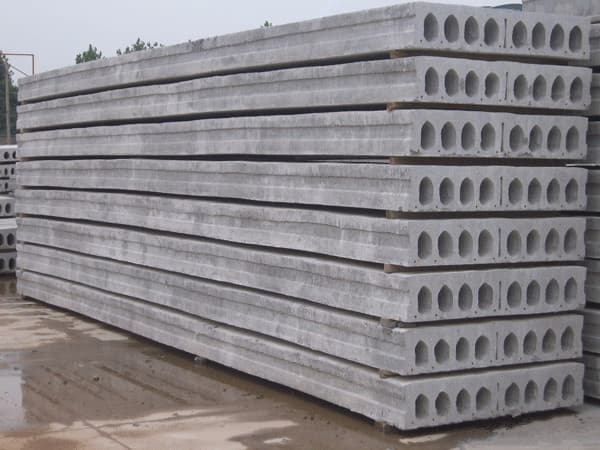
When parking garage decks show joint stepping, tire thumping, or longitudinal cracks along double-tee flanges, facility staff need a disciplined way to record what they see before bringing in the engineer of record.
Deck distress can come from more than one source; this guide records observations and leaves cause assessment to the engineer of record. In a 2015 account, engineer Lawrence E. Keenan described one welded erection-bar connection detail that can develop fatigue cracking after enough cycles of traffic-induced load reversal. This guide uses that account and later field-repair literature to describe the mechanism and what to record.
Why vehicular wheel traffic induces cyclic weld fatigue
In The Construction Specifier ("What's wrong with my precast concrete garage?", June 1, 2015), Lawrence E. Keenan, PE, AIA, describes double-tee construction as widely used for parking garages, with flanges serving as wearing surface and lateral diaphragm, and notes deck-connection maintenance and repair as a common problem. While connections resist seismic loads, he writes that vehicular live load deflection was historically treated as small and overlooked during design.
In the welded erection-bar detail Keenan describes, relative deflection across the joint reverses connection loading as wheels cross; the erection bar resists this movement, subjecting welds to out-of-plane shear and bending about an axis parallel to the joint.
Keenan explains that fatigue weakens materials through cyclic loading. In this configuration, connection geometry creates a notch at the fillet weld root that precipitates crack initiation. With enough cycles, stress reversals propagate cracks until the weld severs completely along the outer face.
Structural mechanics: unpropped cantilevers and longitudinal deck cracking
In a PCI paper (Distress and Repair of Precast Parking Structure Decks), Tarara, Lee, Peterson, and Meinheit explain that double-tee flanges are typically designed as propped cantilever beams, with the connector as prop support, and as continuous beams between stems.
In decks built on this assumption, losing the connector that serves as prop support leaves the flange tip acting like an unpropped cantilever, with stresses increasing when wheel loads sit near the tip. Tarara et al. document that longitudinal cracks typically occur where connections have failed and applied moment exceeds the cracking moment; stresses then transfer to adjacent connectors, potentially causing progressive failures.
In field-topped systems, Tarara et al. observe that connection distress is typically lower than in pre-topped decks when cast-in-place toppings transfer forces between members.
Historical code commentary and connection geometry limitations
In his 2015 feature and 2016 technical paper, Keenan reviewed historical code treatment. He noted that editions such as ACI 318-11 provided general precast criteria but contained no explicit provisions for cyclic fatigue of welded flange connections.
Keenan noted key historical restrictions: the 2007 AWS D1.6 prohibited fillet welds where bending about the longitudinal axis causes tension at the weld root; the 2013 AISC Steel Design Guide 27 cautioned against stress concentrations, eccentricities, and fillet welds to limit fatigue problems; and the 2010 AWS D1.1/D1.1M required calculated stresses to include eccentricity.
Thermal expansion adds complexity: Keenan noted stainless steel expands roughly 50 percent more than mild steel when heated, which can crack concrete during erection welding; Tarara et al. likewise emphasize that welding heat during repairs must be controlled to avoid cracking adjacent concrete.
Field investigation: systematic observations without premature assumptions
An engineer-directed investigation tracks five diagnostic areas:
- Map distress locations and elevations: Record whether stepping and cracking are confined to single joints or span multiple bays, noting approximate elevations. This guide does not assign a cause from a walkthrough; submit the data to the engineer for interpretation.
- Dynamic displacement observation: Relative joint displacement can be observed during normal traffic and measured with dial gauges when the engineer specifies; excessive displacement indicates possible connector failure, not severed steel.
- Selective joint sealant removal: Connection distress is not always obvious without removing sealant at the joint top to inspect connector components and concrete surfaces; unsealing requires an approved scope.
- Acoustic sounding under engineering authorization: Corrosion near connections is not always visible, and hammer sounding can help assess incipient delamination; sounding occurs only under an engineer-authorized scope, not facility staff's own selection.
- Visual fracture documentation boundaries: Fatigue fractures show smooth, burnished crack-propagation zones with parallel beach marks at the microscopic level. This guide does not diagnose fatigue from appearance alone; the engineer determines testing needs.
Field observation and diagnostic coordination register
Use this register during walkthroughs to record observations for the engineer of record. Record only conditions observable from safe, normal access; further investigation requires a separately authorized engineer scope:
| Field observation | Field documentation | Mechanism to evaluate | Engineering referral action |
|---|---|---|---|
| Joint stepping and tire thumping | Record location and deflection during normal traffic | Has shear transfer degraded, or does movement reflect camber variance or flexible detailing? | Engineer evaluates data and decides whether selective testing is warranted |
| Longitudinal crack near stem | Map crack length, width, and staining | Is the flange acting as an unpropped cantilever, or does cracking reflect shrinkage or restraint? | Engineer decides what structural assessment, if any, is warranted |
| Cracked or severed weld under sealant | Photograph weld face, root geometry, and gap if sealant removal is authorized | Did cyclic fatigue cause fracture, or did weld fail from installation defects or restraint? | Engineer assesses the detail and decides on further examination |
| Concrete spalling at plate | Record visible conditions (rust staining, spall extent, anchor exposure) and attach any authorized sounding results | Did concrete spall from weld heat, corrosion expansion, or mechanical prying? | Engineer decides on anchor evaluation, further testing, and repair scope |
| Multi-bay elevation gradient | Record observed elevation differences along column lines, bearings, and joints | Do elevations indicate foundation movement, bearing walkout, or localized joint distress? | Engineer decides whether a survey or further investigation is warranted |
Historical repair taxonomy and engineering boundaries
Tarara et al. classify historical flange connection repairs observed in past parking deck remediations into four categories:
- In-kind repairs: Rewelding the slug bar to the connector faceplates, or installing a replacement connector where distress is severe. Repeated poor performance can be expected unless the original design changes, and welding heat must be controlled to avoid cracking adjacent concrete.
- Externally attached steel members: Fastening supplemental steel members to the flange undersides across the joint, used primarily to address out-of-plane shear transfer.
- Concrete shear-friction repairs: Removing the existing connection and placing new cast-in-place concrete between flanges to transfer forces by shear friction.
- Joint doweling repairs: Placing a bar or proprietary biscuit into a saw-cut slot across the joint, bonded to the slot walls to transfer load between adjacent flanges.
This historical taxonomy summarizes past practice, not a repair recommendation. Selection and detailing of any repair remain the engineer of record's responsibility, including whether diaphragm capacity, thermal movement, or nearby expansion joints need addressing.
Compiling an investigation package for engineering review
Compile an organized documentation package before commissioning repairs, limited to what is observable during a normal walkthrough plus any engineer-authorized findings:
- Structural drawings showing double-tee dimensions and connection details
- Circulation plans identifying drive aisles, turning lanes, and ramps
- Distress maps locating stepped joints, cracked welds, spalls, and cracks
- Deflection observations during normal traffic, including any dial-gauge measurements the engineer specifies
- Photographs of exposed connection hardware and welds following approved sealant removal
For assistance organizing field records, contact the PRECAST.WORLD technical desk. Clarifying whether the garage shows joint stepping, stem cracking, or exposed distress helps organize context, while evaluation and repair decisions stay with your engineer.