Technical Articles
PPVC / MiC Concrete Modules: Lifting Rigging, Landing Alignment Tolerances & Grout Sleeve NDT Verification — Field Inspection Manual
An authoritative site execution and QA/QC inspection manual for volumetric precast concrete MiC/PPVC modules, covering factory center-of-gravity verification, crane rigging mechanics, wind gust thresholds, landing alignment tolerances, bedding sealing, and non-destructive grout sleeve integrity testing.
Volumetric Precast Concrete Modular Construction—designated as Modular Integrated Construction (MiC) in Hong Kong and the United Kingdom, or Prefabricated Prefinished Volumetric Construction (PPVC) in Singapore—represents the leading edge of industrialized modern methods of construction (MMC). By manufacturing fully fitted three-dimensional concrete boxes in an off-site factory environment complete with architectural finishes, integrated MEP risers, factory-glazed facades, and pre-plumbed bathroom pods, on-site labor requirements are reduced by up to 70% and superstructure delivery schedules are accelerated by 30% to 50%.
However, volumetric concrete modular construction shifts project critical-path risks from long-term site casting to high-consequence erection operations. A single volumetric concrete module typically weighs between 25 and 45 metric tonnes (55,000 to 100,000 lbs). The structural dead load is inherently eccentric due to consolidated wet service cores and asymmetrical architectural envelopes. Once lifted, a module acts as a massive bluff aerodynamic body with an exposed sail area of 30 to 45 square meters, vulnerable to dynamic wind gusts. Furthermore, multi-story structural stability and seismic ductility rely completely on grouted rebar splice sleeves concealed inside precast columns, where visual inspection is impossible once modules are landed.
This technical inspection manual outlines the field execution protocols, geometric tolerance budgets, rigging mechanics, joint bedding sealing, and non-destructive testing (NDT) verification workflows required by project directors, lifting supervisors, general contractor QA/QC teams, and resident engineers.
1. Factory Despatch Verification & Rigging Geometry (Pre-Lifting Gate)
Before any volumetric module is loaded onto heavy-haul low-bed transport trailers or admitted to the jobsite staging buffer, the precast manufacturer and general contractor QA representative must execute two mandatory quality verifications at the factory gate:
- Calibrated 4-Point Electronic Weighing*: The module must be weighed using calibrated load cells placed beneath each corner support pad. Off-center placement of consolidated bathroom pods (sanitary fixtures, ceramic wall/floor tiles, waterproof screeds) and heavy facade curtain walls routinely shifts the physical Center of Gravity (CoG) by 200 mm to 600 mm away from the geometric centroid (and up to 1.8 m in high-density wet pod / MEP corridor corner configurations, representing up to 65% load concentration toward one end). The exact coordinates of the physical CoG (ex, ey) and tare mass must be stamped on the delivery ticket.
- 3D Laser Scanning of Starter Dowels and Sleeve Cavities*: A terrestrial 3D laser scan or precision optical survey of all bottom grout sleeve inlet sockets and top protruding starter dowels (diameter 25 mm to 32 mm) must be conducted. The relative spatial coordinates must match the interface tolerance model within +/-2.0 mm to guarantee dowel entry during landing.
Rigging Frame Architecture: Spreader Frame vs. Direct Bridle Slings
Direct multi-leg bridle rigging without an intermediate spreader beam is *strictly prohibited for volumetric concrete modules, unless the module and lifting anchors are specifically engineered and approved by the Engineer of Record (EOR) for inclined tension. Direct angled slings exert severe inward lateral forces (F_horiz = T cos theta) at the top corners. For a 35-tonne module rigged at a 45-degree sling angle, each corner is subjected to over 85 kN of horizontal crushing force, which readily fractures thin unreinforced eave sections (100 mm to 150 mm thick) and cracks window lintels.
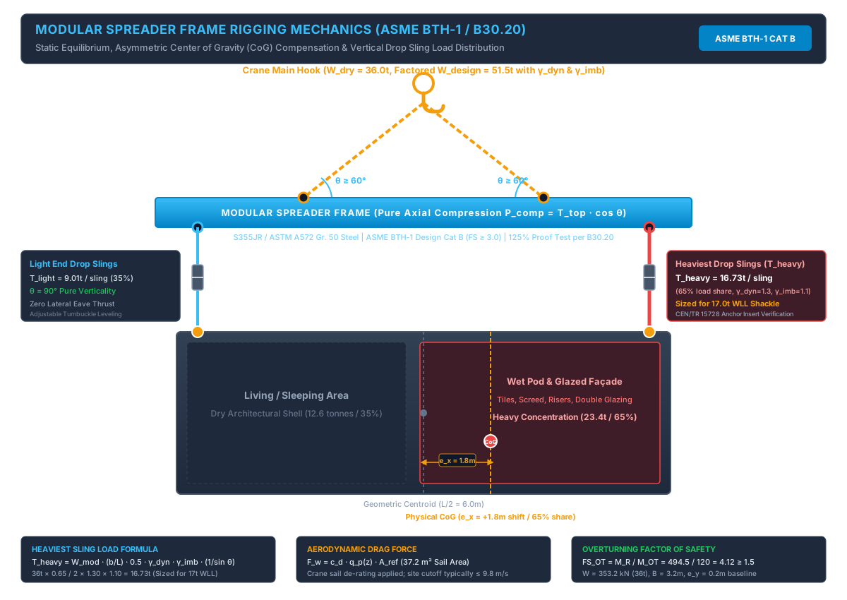
To eliminate lateral thrust, the rigging assembly must utilize an *engineered modular spreader frame* (e.g., Modulift CMOD modular series or custom heavy box-girder frames fabricated from structural steel S355JR / ASTM A572 Grade 50):
- Top Slings*: Connect the central crane hook to the corner padeyes of the spreader frame at an angle theta >= 60 degrees. The top slings carry tensile forces that place the tubular spreader struts into pure axial compression, where structural steel exhibits maximum efficiency.
- Vertical Drop Slings: Connect the spreader frame bottom shackles directly to the cast-in precast module lifting inserts. Because the drop slings hang at exactly 90 degrees (pure verticality), they exert zero lateral compressive force* on the module eaves.
- Adjustable Turnbuckles*: Each vertical drop sling must incorporate a calibrated high-strength turnbuckle (or modular chain shortener) to compensate for the measured CoG eccentricity, ensuring the module flies perfectly level (levelness tolerance <= 1:500).

Governing Field Rigging Formula: Heaviest Sling Leg Load
In a 4-point pick where the Center of Gravity is shifted longitudinally towards one end, the load is distributed unequally. Let the distance between lifting centerlines be $L$. Denoting the longitudinal distance from the light-end lifting point to the center of gravity as $b$, and the distance from the heavy-end lifting point to the center of gravity as $a$ (where $a + b = L$ and $b > a$), moment equilibrium about the light end dictates that the heavy end carries the fraction $b / L$ of the total module weight. Sizing for each of the two heavy-end slings $T_{heavy}$ follows:
$$T_{heavy} = W_{module} \cdot \left(\frac{b}{L}\right) \cdot \frac{1}{2} \cdot \gamma_{dyn} \cdot \gamma_{imb} \cdot \frac{1}{\sin \theta}$$
Where:
- $W_{module}$ is the total factored module weight including factory finishes and rigging gear allowance;
- $b / L$ is the load share ratio carried by the heavy end (e.g., $b/L = 0.65$ when 65% of mass is concentrated towards that end);
- $\gamma_{dyn} = 1.30$ is the *dynamic amplification factor for crane hoisting per ASME B30.20 and PCI Design Handbook*;
- $\gamma_{imb} = 1.10$ is the rigging inequality factor for statically indeterminate 4-point picks without hydraulic equalizers;
- $\theta$ is the sling angle to the horizontal (strictly $\theta = 90^\circ$, $\sin 90^\circ = 1.0$ for vertical drop slings).
For a 36-tonne module with 65% mass shift ($b/L = 0.65$), each of the two heavy-side vertical drop slings carries $36.0 \times 0.65 / 2 \times 1.30 \times 1.10 = 16.73\text{ tonnes}$ of factored dynamic tension, dictating a minimum 17-tonne Working Load Limit (WLL) shackle and certified lifting anchor. *Rigging Statics & Indeterminacy*: In a 4-point rigid spreader assembly, the structural load is statically indeterminate. Assuming each heavy-end sling carries exactly half the heavy-side load ($0.5$) represents an idealized condition achievable only with adjustable turnbuckle leveling. In field practice, minor sling length discrepancies and dynamic sway induce unequal distribution; applying $\gamma_{imb} = 1.10$ establishes a conservative design envelope ($16.73\text{ tonnes}$) ensuring hardware safety.
Rigging Certification and Anchor Standards
| Hardware Component | Governing Standard | Required Factory / Jobsite Certification | Minimum Factor of Safety |
|---|---|---|---|
| Modular Spreader Frame | ASME BTH-1 / EN 13155 | Design Category B, Service Class 1; 125% Proof Load Test Certificate per ASME B30.20 | 3.0 (on yield) / 1.25 proof load |
| Forged Lifting Shackles | EN 13889 / ASME B30.26 | Grade 6 / Grade 80 alloy steel; manufacturer test certificate with embossed heat traceability | 5.0 (on ultimate tensile strength) |
| Cast-in Lifting Inserts | CEN/TR 15728 / VDI/BV-BS 6205 | Precast manufacturer evaluation report for cracked concrete C50/60 with closed perimeter ties | 3.0 (handling) / 4.0 (public safety) |
| Wire Rope Drop Slings | ISO 2408 / ASME B30.9 | 6x36 class IWRC galvanized steel wire rope with pressed steel ferrule thimbles | 5.0 (on breaking strength) |
2. Crane Hoisting & Aerodynamic Wind Engineering
A standard volumetric precast residential box (length $12.0\text{ m}$, width $3.2\text{ m}$, height $3.1\text{ m}$) presents a massive broadside aerodynamic surface of $A_{ref} = 12.0 \times 3.1 = 37.2\text{ m}^2$. When suspended high above ground level by a crawler crane or luffing-jib tower crane, wind interaction creates horizontal drag, aerodynamic vortex shedding, and torsional yawing.
Governing Field Wind Drag Formula
The characteristic horizontal wind force $F_w$ acting on the suspended module during hoisting is evaluated per *EN 1991-1-4* and crane manufacturer aerodynamic charts:
$$F_w = c_d \cdot q_p(z) \cdot A_{ref}$$
Where:
- $c_d = 1.35$ is the aerodynamic drag coefficient for a rectangular bluff body with sharp precast edges;
- $q_p(z) = \frac{1}{2} \rho_{air} v_{gust}^2(z)$ is the peak velocity pressure at hook elevation $z$;
- $A_{ref}$ is the projected windward surface area ($37.2\text{ m}^2$).
Under a gust velocity of $v_{gust} = 10.0\text{ m/s}$ ($36\text{ km/h}$, $\rho_{air} = 1.25\text{ kg/m}^3$), the peak velocity pressure is $q_p = 0.5 \times 1.25 \times 10.0^2 = 62.5\text{ Pa} = 0.0625\text{ kPa}$. The lateral drag force acting on the module reaches:
$$F_w = 1.35 \times 0.0625\text{ kN/m}^2 \times 37.2\text{ m}^2 = 3.14\text{ kN} \approx 320\text{ kgf}$$
If wind speeds increase to $14\text{ m/s}$ ($50\text{ km/h}$), the drag force doubles to $6.15\text{ kN}$, causing uncontrolled module spinning that will overpower hand taglines and risk collision with adjacent structures.
Crane Capacity De-rating and Project Wind Cutoffs
- Crane Manufacturer Load Chart De-rating*: Mobile and crawler crane manufacturers (e.g., Liebherr, Demag, Kobelco) define lifting capacity charts assuming a standard load sail area of $A_w / W_{load} \le 1.2\text{ m}^2/\text{tonne}$. When the sail area ratio exceeds $1.2\text{ m}^2/\text{tonne}$ (common for lightweight or large-aspect modules), crane capacity and maximum permissible wind speed must be de-rated in accordance with the crane's specific wind reduction tables.
- Site Wind Thresholds: Site lifting procedures must adopt the lesser of the crane manufacturer's de-rated wind limit and the project wind safety plan threshold (typically capped at $9.8\text{ m/s}$ / $22\text{ mph}$*).
- Statutory Regional Stop-Work Triggers: - Singapore: In accordance with workplace safety and health guidelines, lifting operations must cease immediately upon activation of regional lightning risk alerts or when site anemometers register gusts exceeding the de-rated crane wind limit. - Hong Kong*: Erection operations must halt upon issuance of tropical cyclone or strong wind warnings by the observatory, or when masthead anemometers register wind speeds exceeding the de-rated site threshold.
Rigging Tagline Control Protocol
Each lifted module must be controlled by a *minimum of two diagonal synthetic taglines* (minimum diameter 16 mm braided polypropylene or nylon, length >= 25 m). Taglines must be hitched to designated lower corner brackets, never around pre-hung electrical cables, door handles, or window mullions. Tagline riggers must wear anti-slip leather gloves and maintain designated clear safety travel paths free of tripping hazards.
3. Landing Alignment, Tolerance Budget & Temporary Anti-Overturning Restraints
The landing phase is the most delicate operational sequence on site. A multi-tonne module must be guided down over 8 to 16 protruding vertical starter rebar dowels (diameter 25 mm to 32 mm) projecting 200 mm to 350 mm from the underlying precast floor or podium.
Perimeter Alignment Guidance System
To prevent protruding rebar from striking the concrete bottom edges and jamming the grout sleeve entries, the contractor must install *machined steel guide pins and conical alignment sleeves*:
- Corner Guide Pins (Guide Cones)*: Heavy-duty tapered steel guide cones ($h = 150\text{ mm}$) are threaded onto the four corner starter bars.
- As the module descends within 300 mm of the landing plane, the crane hoist speed is switched to micro-inching mode ($v \le 0.5\text{ m/min}$).
- The corner guide cones self-center into the flared bell-mouths of the corner grout sleeves, guiding all intermediate rebars cleanly into their respective sleeves without manual pry-bar prying.
Sub-Base Leveling Shim Packs
Each precast module lands upon pre-positioned high-strength structural steel leveling shim packs ($100\text{ mm} \times 100\text{ mm}$ square steel plates with thicknesses ranging from $1.0\text{ mm}$ to $15\text{ mm}$):
- Shim Pack Elevation*: Surveyed by digital optical level to within $\pm 1.0\text{ mm}$ relative to the benchmark building datum before the crane lifts the module.
- Total Bedding Joint Thickness: Strictly maintained between $15\text{ mm}$ and $30\text{ mm}$*. Bedding joints thinner than $15\text{ mm}$ impede complete grout mortar flow during horizontal joint packing; joints exceeding $30\text{ mm}$ induce excessive bedding creep and require structural redesign / shear keys.
- Corrosion Protection*: Steel shims must be hot-dip galvanized or coated with zinc-rich epoxy primer to prevent rust staining and expansive corrosion within the joint.
Dimensional Tolerance Budget (BCA PPVC Guidelines & Project PQP)
| Geometric Parameter | Permissible Individual Tolerance | Multi-Storey Cumulative Limit | Corrective Action if Exceeded |
|---|---|---|---|
| Individual Module Plan Position (X, Y) | +/- 5.0 mm | +/- 10.0 mm over building length | Adjust micro-positioning screw jacks prior to crane release |
| Storey-to-Storey Vertical Plumbness | <= 3.0 mm per 3.0m storey height | <= 1/1000 (10 storeys ~30m <= 30mm); project PQP may tighten to <= 15mm (~1/2000) | Compensate via differential steel shim stack adjustment on next level |
| Inter-Module Horizontal Gap (Joint Width) | 20.0 mm (+/- 5.0 mm) | 15 mm min / 30 mm max | Adjust joint backer rod diameter and structural sealant depth |
| Floor Level Discrepancy Across Adjacent Modules | <= 2.0 mm | <= 5.0 mm overall floor plate | Apply polymer-modified leveling screed before floor finish installation |
Temporary Wind Overturning Stability & Tieback Connection
A 3D concrete box has a broad footprint width ($B = 3.0 \sim 3.6\text{ m}$) that provides a substantial inherent gravity restoring moment $M_R$:
$$M_R = W_{module} \cdot \left(\frac{B}{2} - e_y\right)$$
For a 35-tonne module ($W = 343\text{ kN}$) with width $B = 3.2\text{ m}$ and transverse eccentricity $e_y = 0.2\text{ m}$, the restoring moment is $M_R = 343 \times (1.6 - 0.2) = 480.2\text{ kN}\cdot\text{m}$. Even under a strong storm gust producing an overturning moment of $M_{OT} = 120\text{ kN}\cdot\text{m}$, the gravity safety factor is:
$$FS_{OT} = \frac{M_R}{M_{OT}} = \frac{480.2}{120} = 4.0 \ge 1.5\text{ (Mandatory statutory minimum)}$$
However, to resist wind aerodynamic vortex suction, prevent sliding on smooth steel leveling shims, and lock in tight multi-unit alignment, *each module must be secured with structural tieback connection plates* before releasing the crane hook:
- Horizontal Inter-Module Tie Plates*: Heavy-duty structural steel tie plates ($t = 12\text{ mm} \sim 16\text{ mm}$, Grade S355 / ASTM A36) bolted across adjacent module corner columns using high-strength structural bolts (M24 / M27 Grade 8.8) torqued to specified clamping values.
- Vertical Dowel Friction Locking*: Tight-fitting guide dowels and perimeter tie brackets lock the bottom corners against lateral shear sliding.
- Crane Hook Release Sign-off*: The lifting supervisor and QA inspector must both verify and sign that all leveling shims are fully bearing and perimeter tie bolts are tightened before signaling the crane operator to slacken and unhook the hoist line. Crane unhooking does not require waiting for sleeve grout curing, provided the temporary tie plates are torqued.
4. Bedding Joint Sealing, Grout Sleeve Pumping & Slurry Rheology
The structural load path of high-rise precast modular towers relies on *Grouted Rebar Splice Sleeves (RSS)* embedded in the precast columns to resist tension uplift, shear, and seismic overturning moments. Once cured, the sleeve develops ductile Type 2 mechanical splice capacity (>= 125% of specified rebar yield strength $f_y$ per ACI 318-19 Section 25.5.7 and ISO 15835-1).

The Number One Field Failure Mode: Horizontal Bedding Joint Leakage
Field experience confirms that *the vast majority of grout sleeve void defects stem from failure of the horizontal bedding joint seal, rather than structural defects in the sleeve casting itself*. In a standard column joint, several grout sleeves connect into a shared horizontal bedding mortar cavity. When pressurized grout slurry (0.2 to 0.4 MPa) is pumped into the sleeves:
- If the perimeter bedding mortar seal is poorly packed, the high injection pressure blows out the mortar dam.
- Grout slurry escapes across the floor slab. The slurry column inside the vertical sleeves immediately sinks, creating unfilled air cavities (50 mm to 150 mm) at the critical top anchorage zone.
- Because the leak occurs behind precast facade skirts or inside service chases, it frequently goes undetected until post-curing NDT.
Compartment Sealing Execution Protocol
- Joint Chamber Compartmenting*: Subdivide the continuous horizontal joint into discrete watertight chambers (typically restricted to <= 2.0 m in length, enclosing 2 to 4 sleeves per chamber) using internal dividing dams.
- Zero-Slump Dry-Pack Mortar Damming*: Pack the joint perimeter with high-strength non-shrink dry-pack repair mortar (water-cement ratio w/c <= 0.28). Thoroughly tamp the mortar with a hardwood tool and steel hammer until dense and flush. Alternatively, use pre-compressed high-density closed-cell EPDM foam gaskets bonded with structural polyurethane adhesive.
- Water Leakage Air Test*: Prior to grouting, seal all sleeve vent ports except one. Connect a low-pressure air tester (0.05 MPa / 7 psi) to verify airtightness. Any bubbling along the mortar seam indicates an immediate repair requirement before slurry is mixed.
High-Performance Grout Material Specifications
Grout for precast modular sleeves must meet strict rheological and mechanical performance standards conforming to *JG/T 408 (High-Performance Grout for Couplers) and EN 1504-6, with ASTM C1107 Grade C* serving as baseline reference:
| Property Parameter | Governing Standard | Mandatory Acceptance Threshold | Field QC Check Frequency |
|---|---|---|---|
| Fluidity / Efflux Time | JG/T 408 (Truncated Cone) / ASTM C939 (Flow Cone) | Initial spread >= 300 mm (truncated cone per JG/T 408); or 20 to 30 seconds efflux (ASTM C939 flow cone) | Every batch mixed on site |
| Bleed Water Rate | JG/T 408 / ASTM C940 | 0.0% (Zero Bleed at 3 hours per JG/T 408); complete settlement void prevention | Daily pre-shift trial batch |
| Early Compressive Strength (1 Day) | GB/T 17671 (40x40x160mm) / EN 12190 | >= 35.0 MPa (enables early structural load transfer) | 1 set of 3 prisms per shift / pour |
| Mid-Term Compressive Strength (3 Days) | GB/T 17671 (40x40x160mm) / EN 12190 | >= 60.0 MPa (supports subsequent floor stacking) | 1 set of 3 prisms per shift / pour |
| Final Compressive Strength (28 Days) | GB/T 17671 (40x40x160mm) / EN 12190 | >= 85.0 MPa (exceeds C50/60 host concrete; ASTM C1107 min is 34.5 MPa) | 1 set of 3 prisms per shift / pour |
| Vertical Expansion Rate | JG/T 408 / ASTM C1090 | +0.02% to +0.50% at 3h per JG/T 408; positive non-shrink expansion | Certified manufacturer mill ticket |
Pressurized Grout Pumping Execution
All sleeve grouting must be executed using a *continuous progressive cavity pump (mono pump or screw pump)* with variable pressure control (0.2 to 0.4 MPa). Piston pumps and gravity pouring are strictly prohibited because they introduce pulsating air bubbles and inadequate consolidation.
- Connect the injection nozzle securely to the lowest inlet port of the first sleeve in the compartment.
- Pump continuously at steady low velocity (3 to 5 liters/minute) until a thick, uniform stream of grout completely free of air bubbles discharges from the upper vent port.
- Seal the upper vent port with a heavy-duty tapered rubber plug or threaded sealing cap while pumping continues.
- Hold injection back-pressure at 0.2 MPa for 10 seconds to consolidate the matrix against the internal rebar deformation ribs.
- Clamp and seal the inlet port. Repeat sequentially for all sleeves in the compartment.
- Mandatory Inspection*: 30 to 45 minutes after grouting, the QC inspector must re-open a sample of top vent plugs. If any slurry settlement or recession greater than 5.0 mm has occurred, the cavity must be immediately topped up using a manual pressure injection syringe.
5. Multi-Tier NDT Quality Verification & Remediation Protocol
Because the rebar splice sleeve is fully encased inside dense precast concrete cover, post-grouting quality assurance requires robust non-destructive testing (NDT) methodologies. Direct diamond core drilling through a load-bearing column sleeve is *strictly prohibited by all international codes* because it severs the ductile iron confining shell and cuts the internal vertical rebar.
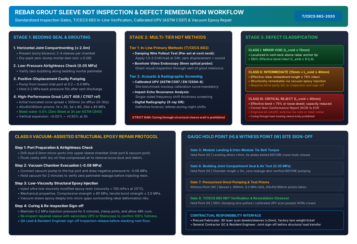
Tier 1: Pre-Installed In-Line & Direct Port Verification (T/CECS 683-2020)
Recognized internationally as the most reliable quality assurance methodology, in-line verification tools are installed directly inside the sleeve cavity before casting:
- Damping Wire Pullout Method (Pre-set Steel Wire)*: A calibrated high-tensile spring steel wire with an anchoring foot is pre-positioned at the sleeve vent neck (top 30 mm). After 24 hours of curing, a calibrated digital pull-tester applies a tensile load of 1.0 kN to 2.0 kN. If the grout is fully consolidated around the wire, it resists pullout with negligible displacement. If an air void exists at the top, the wire pulls clean out, providing instant verification per T/CECS 683 testing protocols.
- Embedded Acoustic / Electrical Resistance Sensors*: Miniature passive acoustic or conductivity sensor probes pre-wired to the top vent plug detect dense cement slurry contact, recording an automated digital timestamped log on the site QC dashboard.
- Borehole Video Endoscopy (Direct Port Inspection)*: A 6.0 mm flexible digital fiberscope equipped with LED lighting is inserted directly through the upper vent port into the sleeve cavity. The high-definition camera visually inspects the grout meniscus, verifies rebar rib embedment, and directly measures void depth using a calibrated probe scale.
Tier 2: External Non-Destructive Screening (ASTM C597 & Acoustic Resonance)
- Ultrasonic Pulse Velocity (UPV per ASTM C597 / EN 12504-4): Transducer and receiver probes (54 kHz typical, couplant verified) are coupled to opposite faces of the column in a pitch-catch orientation. Critical Requirement*: There is no universal acoustic velocity threshold. The contractor must manufacture full-scale project calibration blocks containing sound sleeves and artificial voids (10 mm, 25 mm, 50 mm). In sound high-strength grout, P-wave velocity typically reaches approximately $4,300 \sim 4,600\text{ m/s}$ (example benchmark). The presence of an air pocket causes wave diffraction around the steel sleeve, dropping velocity below $3,500\text{ m/s}$ and inducing severe signal attenuation ($> 12\text{ dB}$ on calibrated specimens).
- Impact-Echo Resonance Analysis*: A mechanical impactor introduces transient stress waves from a single accessible column face. Frequency spectrum shifts screen for reflective void interfaces behind the concrete cover, providing rapid single-sided screening across dense sleeve groups.
- Digital Radiography (X-Ray DR)*: Utilized as a definitive forensic referee method conducted during controlled night shifts. High-resolution digital detector arrays directly image rebar anchorage length and void meniscus geometry without destructive drilling.
Defect Classification and Remediation Matrix
| Defect Severity Class | Measured Void Characteristics | Structural Bond Impact | Mandatory Remediation Protocol |
|---|---|---|---|
| Class I (Minor) | Void depth <= 15 mm localized in vent neck above rebar tip | Zero loss of effective rebar anchorage length (L_emb >= 8 d_b fully intact) | Drill 8mm clean port into vent; flush with oil-free air; inject high-strength cementitious micro-grout; re-plug |
| Class II (Intermediate) | Void depth 15 mm to 40 mm; rebar bond length >= 75% of design embedment | Partial loss of bond reserve; remediable by approved structural resin | Execute **Vacuum-Assisted Epoxy Injection**: drill twin 6mm ports, evacuate cavity to -0.08 MPa, pressure-inject ultra-low viscosity structural epoxy (<100 mPa.s, compressive strength >=80 MPa, bond >=3.5 MPa per engineer-approved repair procedure) |
| Class III (Critical Non-Conformance) | Void depth > 40 mm, rebar bond < 75%, or loose starter dowel | Severe loss of tension development; joint cannot transfer design seismic / wind forces | Raise formal NCR to Engineer of Record (EOR). Execute structural retrofits: external post-tensioned tie rods, structural steel encasement collars, or engineered corner brackets. Destructive coring through sleeve body prohibited. |
6. QA/QC Hold Points, Contract Interfaces & Site Sign-off Matrix
To guarantee chain-of-custody accountability and prevent cross-trade contractual disputes between precast fabricators, logistics haulers, crane erection sub-contractors, and the general contractor, the following *Quality Inspection Hold Point (H) and Witness Point (W) Matrix* must be integrated into the Project Quality Plan (PQP):
| Inspection Gate | Verification Check Item | Inspection Type | Responsible Sign-off Parties |
|---|---|---|---|
| Gate 1: Factory Despatch | Tare weight stamped, CoG coordinates verified, 3D laser scan of dowels/sleeves within +/-2mm | Hold Point (H) | Precast QA Manager & Resident Engineer (RE) |
| Gate 2: Rigging Rig-up | Spreader frame proof test cert (ASME B30.20), shackle WLL, turnbuckle levelness adjustment | Hold Point (H) | Lifting Director & Rigging Supervisor |
| Gate 3: Weather Clearance | Site anemometer < 9.8 m/s (or de-rated crane wind limit), zero statutory lightning/cyclone warnings | Witness Point (W) | Site Safety Officer & Crane Operator |
| Gate 4: Sub-Base Shimming | Steel shim packs set to +/-1.0mm datum; joint gap verified between 15mm and 30mm | Hold Point (H) | Lead Land Surveyor & Erection Supervisor |
| Gate 5: Landing & Tie Bolting | Module plan position within +/-5mm; inter-module structural tie plates bolted and torqued before crane unhooking | Hold Point (H) | General Contractor QC Lead & Structural RE |
| Gate 6: Bedding Joint Seal | Joint compartmentalized <=2m; dry-pack mortar dam cured to >=15 MPa; 0.05 MPa air test verified | Hold Point (H) | Grouting Foreman & QC Inspector |
| Gate 7: Pressurized Grouting | Flow cone efflux 20-30s; continuous pump flow; 0.2 MPa back-pressure held; 40x40x160mm prisms taken | Witness Point (W) | Grouting Specialist & Third-Party Inspector |
| Gate 8: NDT Acceptance | 100% damping wire pullout / calibrated UPV scan completed; all Class I/II repairs signed off | Hold Point (H) | Accredited NDT Level II/III & Engineer of Record |
Summary: Field Rules of Engagement
- Never lift without an engineered modular spreader frame*: Direct angled slings crush module eaves and crack finishes.
- Never trust nominal architectural drawings for weight*: Always weigh modules at the factory to locate the true asymmetric Center of Gravity.
- Respect crane wind de-rating thresholds*: Bluff modular boxes act like giant sails; adhere strictly to crane manufacturer reduction charts and site anemometer cutoffs (typically <= 9.8 m/s).
- Compartment the horizontal bedding joint*: Uncontrolled mortar dam blowout during pressurized pumping is the root cause of sleeve void failures.
- Calibrate NDT on full-scale site benchmark mockups*: Generic textbook acoustic velocity numbers do not reflect composite rebar-concrete-sleeve physics.
- Never core-drill into structural sleeves*: Remediate intermediate voids using vacuum epoxy injection under professional engineering oversight.