Technical Articles
Global Precast Concrete Industry Practice Guide: Market, Engineering, Manufacturing & Site Assembly
An end-to-end technical and commercial practice guide for the global precast concrete industry, covering market economics, structural connections, plant automation, site erection, and defect remediation.
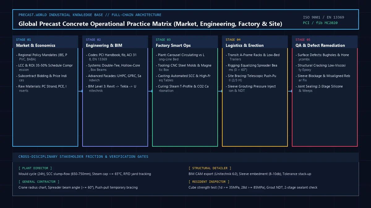
The global precast concrete industry has historically suffered from fragmented execution. Commercial developers evaluate precast strictly on initial material quotation, structural designers produce idealized component geometry without plant demolding considerations, precast manufacturers optimize batch cycle times at the expense of field interface tolerances, and general contractors treat precast erection as an afterthought on jobsites configured for cast-in-place concrete.
Treating precast concrete as an isolated technical product rather than an integrated industrial system is the root cause of project cost overruns, connection misfits, and bitter commercial disputes. A successful precast project requires synchronized coordination across five distinct lifecycle stages: macroeconomic and procurement feasibility, BIM-driven structural engineering, automated factory operations, crane rigging logistics, and jobsite assembly with verifiable non-destructive quality assurance.
This practice guide establishes an end-to-end operational framework for precast factory directors, structural detailers, general contractors, resident inspectors, and equipment suppliers. Design calculations, contract allocations, and site engineering procedures remain under the professional authority of the licensed project engineer of record and designated commercial authorities.
1. Global Market Dynamics, Procurement Policies and Life-Cycle Economics
Precast concrete adoption is not uniform globally; it is shaped by regional labor demographics, environmental carbon mandates, and statutory prefabrication quotas.
Regional Regulatory Drivers and Precast Mandates
- North America*: Driven by the Federal Highway Administration (FHWA) Prefabricated Bridge Elements and Systems (PBES) initiative and accelerated bridge construction (ABC) programs. The Build America, Buy America Act (BABA) under Title IX of the Infrastructure Investment and Jobs Act mandates that manufactured products incorporated into federally funded infrastructure contain greater than 55% domestic component cost, directly impacting imported steel strands and specialized connection hardware.
- European Union*: Governed by the Construction Products Regulation (CPR) and EN 13369:2023 (Common rules for precast concrete products). European Union decarbonization roadmaps penalize high-carbon Portland cement through the Emissions Trading System (EU ETS), accelerating adoption of low-carbon blended binders (CEM II, CEM III) and limestone calcined clay cement (LC3).
- Middle East (GCC)*: Driven by Saudi Arabia Vision 2030 giga-projects (NEOM, Red Sea, Qiddiya) and UAE modular housing programs. The Saudi Standards, Metrology and Quality Organization (SASO) mandates industrial precast building systems to deliver tens of thousands of residential units under aggressive fast-track schedules in hyper-arid, high-sulfate soil environments.
- Southeast Asia*: Singapore’s Building and Construction Authority (BCA) enforces mandatory Prefabricated Prefinished Volumetric Construction (PPVC) on non-landed residential government land sales. Malaysia’s Construction Industry Development Board (CIDB) enforces CIS 18:2023, requiring public building projects exceeding RM 10 million to achieve an Industrialised Building System (IBS) score of at least 70 points.
- East Asia*: China’s Ministry of Housing and Urban-Rural Development (MOHURD) standard GB/T 51129-2017 enforces prefabricated building evaluation standards with minimum 50% assembly rates, backed by floor area ratio (FAR) bonuses and green finance incentives. In Japan, high seismicity drives precast concrete usage under Architectural Institute of Japan (AIJ) precast guidelines and JIS A 5373 prestressed concrete product standards.
Life-Cycle Cost (LCC) and ROI: Precast vs. Cast-in-Place
Comparing precast concrete with cast-in-place (CIP) concrete purely on direct material unit cost ($/m³ or $/ft³) is fundamentally flawed. In initial direct material and fabrication expense, precast concrete typically carries a 10% to 25% cost premium over traditional cast-in-place concrete due to specialized steel molds, factory overhead, crane transport, and high-strength grout sleeves.
However, comprehensive Life-Cycle Cost (LCC) and Return on Investment (ROI) evaluations reveal that precast delivers substantial net commercial savings through schedule compression, labor efficiency, and early revenue generation:
- Construction Schedule Compression*: Factory fabrication runs concurrently with site foundation excavation and civil utility works. Superstructure erection time is reduced by 30% to 50% compared to cast-in-place construction, where each floor requires formwork erection, rebar tying, concrete pour, and a 14-to-28 day curing wait before shoring removal.
- On-Site Labor Reduction*: On-site labor headcount is reduced by 60% to 70%, eliminating carpenters, rebar placers, and vibrator operators. This significantly mitigates overtime wages, worker lodging overhead, jobsite safety accidents, and local skilled labor shortages.
- Interest During Construction (IDC) Savings*: Compressing a 24-month high-rise building schedule to 14 months eliminates 10 months of developer construction loan interest and lowers general contractor site overhead (tower crane lease, site trailers, scaffolding).
- Earlier Commercial Tenancy / Handover*: Delivering a logistics warehouse, multi-family residential building, or data center 6 months early yields immediate operational lease cash flow, often exceeding the entire initial precast fabrication premium.
| Parameter | Traditional Cast-in-Place (CIP) | Precast Pre-Engineered System | Commercial / Technical Impact |
|---|---|---|---|
| Direct Material & Tooling Cost | Lower baseline (standard plywood forms) | 10% - 25% initial premium (steel molds, sleeves) | Offset by total project lifecycle duration |
| Superstructure Floor Cycle | 7 - 12 days per floor | 2 - 4 days per floor | 35% - 50% overall schedule compression |
| Jobsite Labor Density | High (80 - 150 workers on active floor) | Low (15 - 25 workers in erection gang) | 65% reduction in site labor safety risk |
| Weather Sensitivity | High (rain, freezing, wind halts pours) | Negligible (controlled factory curing) | Eliminates cold-weather site heating costs |
| Dimensional Tolerance | ±10 mm to ±20 mm (field timber forms) | ±2 mm to ±3 mm (precision CNC steel molds) | Eliminates wet plastering and leveling beds |
| Concrete Strength & Density | C30 - C40 typical (field variability) | C50 - C90 high-performance SCC / spun | Extended durability and service design life |
Subcontract Bidding, Pricing Rules and Contract Dispute Avoidance
Precast subcontracts frequently generate costly disputes between general contractors and precasters over scope boundaries. Effective risk mitigation requires explicit contractual terms:
- Measurement and Pricing Basis*: Pricing should be clearly structured as either a lump-sum contract per approved architectural/structural set with defined revision thresholds, or unit-rate by net component volume ($/m³) excluding concrete openings, with separate price line items for steel inserts and connection hardware.
- Mold Amortization and Change Order Thresholds*: Steel mold costs represent 15% to 30% of total plant production expense. Contracts must state that repetitive component geometry (minimum 30 to 50 casting cycles per mold) is the economic foundation of the bid. If the architect or engineer introduces variations requiring mold modifications after shop drawing approval, the owner absorbs mold retooling expenses.
- Raw Material Price Escalation Indices*: Multi-year infrastructure projects must tie cement, steel rebar, and prestressing strand prices to published benchmark indices (such as S&P Global Platts Steel Rebar Index or national producer price indices). Escalation adjustment formulas trigger when market prices shift beyond a ±5% deadband.
- Milestone Payment Triggers*: Precasters must not accept terms tying payment solely to site installation. The recommended milestone schedule is: 10% on shop drawing sign-off, 20% on steel mold completion, 30% on factory casting and QC sign-off, 20% upon delivery to yard/site, and 20% on final structural alignment and grouting acceptance.
- Interface Handover Protocol*: Establish clear lines of responsibility. The general contractor is responsible for foundation dowel surveyed locations (within ±3 mm tolerance) and crane access roads. The precaster is responsible for element integrity up to crane hook release. The erection subcontractor is responsible for shimming, plumbing, bracing, and grouting.
Core Raw Material Volatility and Supply Chain Lead Times
- Ordinary Portland Cement (OPC) & Supplementary Cementitious Materials (SCMs)*: Precast requires high early strength (15-20 MPa at 12-16 hours for mold turnaround). Precasters use Type III / CEM I 52.5R high-early cement, blended with 10-25% Grade 100/120 Ground Granulated Blast-Furnace Slag (GGBS) and 5-8% densified silica fume to lower heat of hydration while maximizing 28-day density and chloride impermeability. Lead time for bulk pneumatic tanker delivery: 3 to 7 days.
- High-Tensile Prestressing Steel Strand*: ASTM A416 / ISO 6934 Grade 270 (1860 MPa) low-relaxation seven-wire strands (typically 12.7 mm / 0.5" or 15.2 mm / 0.6" diameter). Minimum tensile strength $f_{pu} = 1860\text{ MPa}$, yield strength $f_{py} \ge 0.90 f_{pu}$, relaxation loss after 1,000 hours at 20°C and 70% initial load $\le 2.5\%$. Lead time for mill coil delivery: 6 to 12 weeks.
- Polycarboxylate Ether (PCE) Superplasticizers*: Third-generation PCE admixtures designed for high-range water reduction ($\ge 25-35\%$) at low water-cementitious ratios ($w/cm = 0.28-0.36$). Must maintain fluidity for 45 minutes without retarding early hydration kinetics. Drum and IBC container shelf life: 6 to 12 months (must be protected from freezing below 2°C).
- Specialized Connection Hardware*: Ductile iron grout sleeves (grade QT450-10 or ASTM A536 65-45-12), high-strength anchoring bolts (Grade 8.8 / 10.9), hot-dip galvanized ferrules, and rare-earth neodymium magnetic chamfers. Sourcing lead times: 8 to 14 weeks for imported certified systems; pre-ordering during early schematic design is mandatory.
2. Structural Engineering, Component Systems and International Design Codes
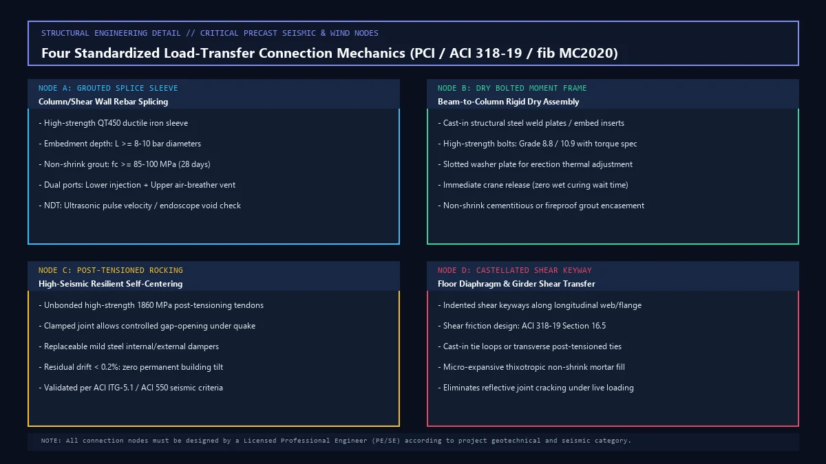
Precast structural design differs fundamentally from cast-in-place design. The structural engineer must evaluate the element through multiple temporary load stages—stripping from mold, storage stacking, highway transport, crane hoisting—before the component ever acts as a permanent composite structure.
High-Performance Structural Component System Design
- Prestressed Double-Tee (DT) Slabs*: Spanning 12 to 25 meters in parking structures, roofs, and industrial floors. Stem dapping at corbel bearings requires dedicated hanger reinforcement to resist re-entrant corner shear concentrations. Flange weld plates transfer in-plane diaphragm shear forces between adjacent tees; flexible mechanical ties prevent fatigue cracking under cyclic truck traffic.
- Prestressed Hollow-Core Slabs (HCS)*: Extruded or slip-formed with longitudinal voids, reducing concrete self-weight by 40% to 50% across 6-to-18 meter spans. Web shear capacity must be verified under transverse cracking per ACI 318-19 Section 22.5. At supporting beams, cores are filled with solid structural concrete over a length of 300 to 500 mm to transfer high bearing reaction forces.
- Segmental Bridge Girders*: Match-cast box girders erected via balanced cantilever or overhead launching gantries. Joints feature multi-toothed castellated shear keys sealed with thixotropic epoxy resin and clamped under permanent longitudinal post-tensioning tendons, satisfying AASHTO LRFD Bridge Design Specifications.
- Precast Beam-Column Moment Frames*: Emulative of cast-in-place frames or semi-rigid jointed systems. Columns utilize multi-tier continuous elements (up to 3 stories) with corbel supports or recessed pockets to seat precast prestressed inverted T-beams, topped with a composite cast-in-place floor screed (minimum 65 to 75 mm thickness with welded wire reinforcement).
- Three-in-One Insulated Sandwich Wall Panels*: Comprising an inner structural concrete wythe (120-180 mm), a continuous extruded polystyrene (XPS) or polyisocyanurate (PIR) insulation core (50-100 mm), and an architectural outer concrete wythe (60-80 mm). Wythes are coupled across the insulation using non-conductive glass fiber reinforced polymer (GFRP) or basalt FRP pin ties. FRP connectors eliminate thermal bridging while accommodating differential thermal expansion between the outer and inner wythes, preventing panel bowing.
- Monolithic Staircases and Balconies*: Precast stairs feature integrated landings cast monolithically. Connections utilize neoprene isolation pads and slotted dowels to prevent stairs from acting as unintentional seismic braces during lateral building sway.
Critical Structural Connections and Joint Mechanics
Precast integrity depends entirely on connection performance under gravity, wind, and seismic reversing cyclic loads:
- Grouted Splice Sleeves (Node A)*: The global standard for vertical rebar splicing in columns and shear walls. A ductile iron sleeve encloses the opposing rebar ends. High-strength non-shrink thixotropic cementitious grout ($f_c \ge 85\text{ MPa}$ at 28 days) is pumped under pressure through the lower injection port until airless grout flows from the top breather port. Bar embedment length $L_e \ge 8 d_b$ ensures full rebar tensile yielding prior to bond failure.
- Dry Bolted Moment and Shear Connections (Node B)*: Steel embed plates cast into precast members are connected using high-strength Grade 8.8 or 10.9 structural bolts through slotted shims. Eliminates wet curing wait times, allowing immediate crane release. Once torqued, the cavity is dry-packed with non-shrink cementitious grout or fireproof mortar.
- Unbonded Post-Tensioned Rocking Connections (Node C)*: Developed for high-seismicity regions (PRESSS program, ACI ITG-5.1). Vertical unbonded post-tensioning tendons clamp precast shear walls to foundation beams. Under severe earthquake ground motions, the joint rocks open at the base, dissipating energy without plastic hinge rebar rupture. Replaceable mild steel internal or external dampers absorb seismic energy, and unbonded tendons snap the structure back to plumb with residual drift under 0.2%.
- Castellated Shear Keyways (Node D)*: Formed along the longitudinal edges of wall panels and bridge box beams. Shear transfer across the joint relies on mechanical concrete key interlock and interface shear-friction reinforcement per ACI 318-19 Section 16.5 and Eurocode 2 EN 1992-1-1 Section 6.2.5. Joints are pressure-grouted with micro-expansive mortar.
- Wet-Joint Cast-in-Place Closure Pours*: Used at floor diaphragm stitches and column-beam intersections where complex multi-directional rebar laps occur. Formwork is clamped tightly against precast edges with foam rubber seals; high-slump micro-concrete ($f_c \ge 40\text{ MPa}$) with synthetic fibers is poured and vibrated to form an emulative monolithic joint.
Architectural Facades and Advanced Cementitious Composites
- Ultra-High Performance Concrete (UHPC)*: Formulated with fine aggregate (< 0.6 mm), silica fume, low water-binder ratio ($w/b = 0.16-0.20$), and 1.5% to 2.5% by volume high-tensile brass-coated micro-steel fibers ($d = 0.2\text{ mm}, l = 13\text{ mm}$). Compressive strength $f_c \ge 120-160\text{ MPa}$, flexural strength $f_r \ge 18-30\text{ MPa}$. Enables extremely thin, lightweight facade rainscreen panels (15-30 mm thickness) spanning up to 4 meters without conventional rebar cages.
- Glass Fiber Reinforced Concrete (GFRC)*: Composed of white Portland cement, silica sand, polymer emulsion, and 3% to 5% chopped alkali-resistant (AR) glass fibers ($ZrO_2 \ge 16.7\%$). Manufactured via simultaneous spray-up or premix casting. Ideal for complex curved, fluid organic facades with panel weight under 50 kg/m².
- Fair-Faced Architectural Concrete*: Formulated using white cement, graded quartz aggregate, lightfast mineral pigments, and stainless steel rebar. Mold surfaces utilize mirror-polished steel, polyurethane liners, or formliners to produce ribbed, fluted, or board-marked textures.
- Translucent Concrete*: High-strength fine mortar embedded with dense arrays of optical glass fibers (0.5 mm to 2 mm diameter, 2% to 5% volume fraction) transmitting natural daylight and artificial silhouette patterns through structural interior partitions and decorative facade panels.
Volumetric Modular Prefabrication (IBS, PPVC, MiC)
Modular Integrated Construction (MiC) and Prefabricated Prefinished Volumetric Construction (PPVC) represent the highest level of prefabrication:
- Structural Module Construction*: Fully three-dimensional reinforced concrete volumetric boxes (typically 3.0-3.6 m width, 6.0-12.0 m length, 3.0 m height, weighing 25 to 40 metric tons).
- Inter-Module Structural Connections*: Vertical load transfer utilizes corner casting blocks with high-tensile tie-rods post-tensioned from the top of the upper module down into the lower module's cast-in anchor box. Horizontal shear transfer relies on shear keys and bolted interlocking plates.
- Joint Waterproofing & MEP Integration*: Perimeter air and water tightness is achieved via continuous multi-stage EPDM/neoprene bulb gaskets compressed under module self-weight, complemented by silicone secondary external seals. Bathroom pods, electrical conduits, plumbing stacks, and internal tile finishes are 90% pre-fitted inside the factory.
BIM Forward Design and Digital Production Data Pipelines
- BIM Level 3 Modeling*: Precast components are designed in full LOD 400 detail using software like Autodesk Revit and Trimble Tekla Structures. Every rebar bend, lifting anchor, grout sleeve, MEP conduit, and chamfer is modeled with zero clash tolerance.
- IFC and Unitechnik Data Exchange*: The BIM model exports structural and geometric data directly into standardized manufacturing formats:
- Unitechnik CAD-CAM (Versions 5.2 and 6.0)*: Generates numeric control files (`.uni`) containing pallet layout, slab boundary outlines, cutouts, reinforcement coordinates, and cast-in part IDs.
- PXML Format*: Data exchange for automated carousel line master computers.
- Direct Machine Automation*: The `.uni` files drive factory automation hardware without manual drawing conversion: laser projectors display element contours on circulating steel pallets, shuttering robots pick and place magnetic side forms, and automated CNC mesh welders straighten, cut, bend, and weld reinforcement mesh sheets.
Multi-National Standards Comparative Matrix
| Design Parameter | North America: PCI Handbook (8th/9th ed) / ACI 318-19 | Europe: EN 13369:2023 / Eurocode 2 (EN 1992-1-1) | China: GB 50010-2010 / GB 50204-2015 |
|---|---|---|---|
| Concrete Design Strengths | $f'_c$ cylinder: 35 - 70 MPa typical | $f_{ck}$ cylinder / $f_{ck,cube}$: C30/37 - C80/95 | $f_{cu,k}$ cube: C30 - C80 |
| Prestressing Strand Standard | ASTM A416 Grade 270 ($f_{pu} = 1860\text{ MPa}$) | EN 10138-3 ($f_{pk} = 1860\text{ MPa}$) | GB/T 5224 ($f_{ptk} = 1860\text{ MPa}$) |
| Concrete Clear Cover ($c_{nom}$) | Interior: 20 mm; Exterior: 38 - 50 mm | Durability-class based ($c_{min} + \Delta c_{dev}$): 25 - 45 mm | Indoor: 15 - 20 mm; Outdoor: 25 - 35 mm |
| Prestress Loss Calculation | Refined step method (PCI Section 5.9) | Time-dependent creep, shrinkage & relaxation (EC2 Cl. 5.10.6) | Sum of instantaneous & long-term losses (GB 50010 Cl. 10.2) |
| Seismic Sleeve Splice Criteria | ACI 318 Type 2: $1.25 f_y$ tensile yield | ETA approval: Static, cyclic & low-cycle fatigue test | JGJ 107 Grade I: $1.15 f_{stk}$ tensile rupture |
| Tolerance Standard | ACI 117 / PCI MNL-135 Tolerance Manual | EN 13369 Annex J (Class A / Class B) | GB 50204 Chapter 9 / JGJ 1 Appendix A |
3. Smart Factory Operations, Automated Manufacturing and Process Engineering
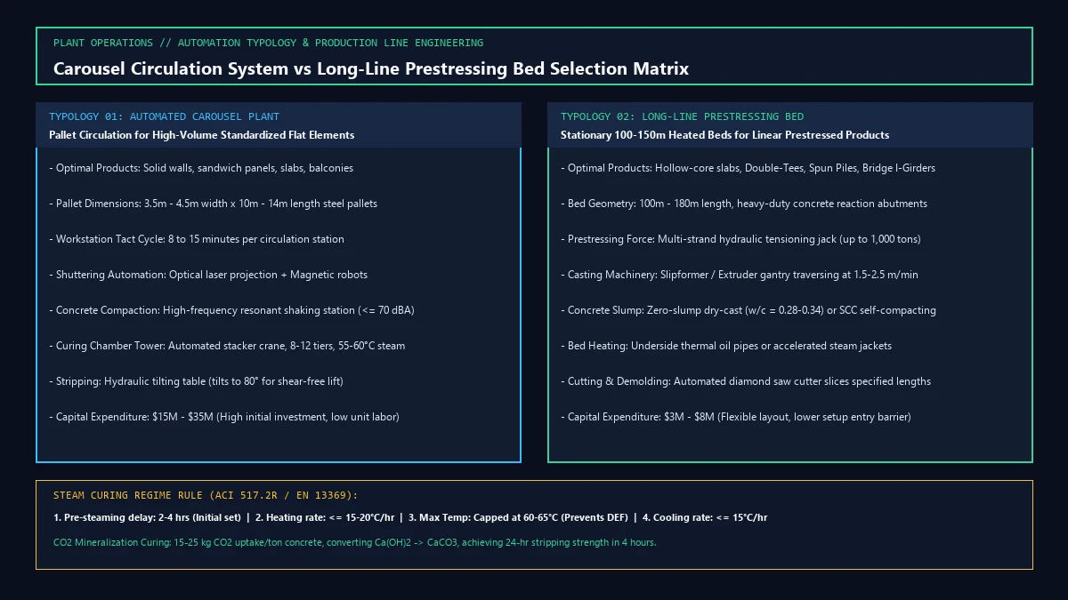
The precast factory is a controlled manufacturing environment where industrial automation transforms wet construction into high-precision engineering.
Plant Master Planning: Carousel Plant vs. Long-Line Casting Beds
Selecting the appropriate plant layout dictates long-term capital efficiency, daily output, and operational flexibility:
- Automated Carousel Plant (Circulating Pallet System)*:
- Mechanism: Steel casting pallets (typical dimensions 3.5-4.5 m width, 10-14 m length) circulate sequentially through dedicated specialized workstations: pallet cleaning, optical laser plot/shuttering robot, rebar placement, concrete casting, vibrating compaction, automated multi-tier vertical curing chamber tower, and hydraulic tilting/demolding station.
- Best Application: Standardized flat elements with high production volume: solid precast walls, insulated sandwich facade panels, double-walls, precast filigree slabs, and modular bathroom pods.
- Operational Metrics: Cycle tact time of 8 to 15 minutes per pallet. High daily volume (up to 1,500-2,500 m² of concrete elements per shift), low manual labor density, and high initial CAPEX ($15M to $35M).
- Long-Line Prestressing Beds (Stationary System)*:
- Mechanism: Fixed, heavy-duty steel beds spanning 100 to 180 meters in length, anchored by massive concrete reaction abutments designed to resist hydraulic prestressing forces up to 500 to 1,200 metric tons.
- Best Application: Linear prestressed structural elements: hollow-core slabs (HCS), Double-Tee beams, bridge I-girders, and spun foundation piles.
- Operational Metrics: Extruder or slipformer gantries travel along the stationary bed at 1.5 to 2.5 m/min. Concrete cures in-situ via bed steam or hot water heating jackets. Elements are saw-cut to exact lengths using automated diamond-blade saws. Lower initial CAPEX ($3M to $8M), high structural versatility, but larger factory footprint requirements.
Precision Tooling, CNC Steel Molds and Rare-Earth Magnetic Shuttering
- Precision Steel Molds*: Fabricated from high-grade structural steel plate (Q345B / S355JR, thickness 6-10 mm) with surface flatness tolerance within $\pm 1\text{ mm}$ across 3 meters. Draft angles of 1° to 3° on vertical side rails are mandatory to prevent surface spalling during element demolding.
- Magnetic Shuttering Systems*: Reusable steel and aluminum side profiles held in place on the steel pallet using integrated neodymium-iron-boron (NdFeB) magnetic boxes. Holding forces range from 9,000 N (900 kg) for 100 mm thin slabs up to 21,000 N (2,100 kg) for 350 mm heavy retaining walls. Magnetic systems eliminate welding, drilling, or bolting to the casting pallet, increasing pallet surface longevity from 2 years to over 15 years.
- Variable-Cross-Section Telescopic Molds*: Hydraulically articulated molds for bridge girders and stadium seating risers, allowing variable web heights and flange widths via remote hydraulic pushers, minimizing changeover retooling downtime from 3 days to 2 hours.
- Elastomeric Formliners & 3D Printed Patterns*: Polyurethane elastomeric liners and 3D printed polymer molds applied to the bed to imprint intricate wood grain, fluted geometric profiles, or relief textures onto the concrete surface.
Automated Rebar Processing and Precise Spacer Positioning
- Automated CNC Mesh Welding*: Reinforcement mesh sheets are assembled by robotic welding lines directly from cold-rolled steel coils, cutting and resistance-welding longitudinal and cross wires to exact mm spacings.
- CNC Stirrup Benders and Rebar Cutters*: High-speed twin-wire automatic stirrup bending machines produce complex closed ties and links at speeds up to 1,200 stirrups/hour with angle accuracy within $\pm 0.5^\circ$.
- Rebar Cover Spacers*: Concrete cover compliance ($c_{nom} \pm 3\text{ mm}$) requires high-density fiber-reinforced concrete spacers or heavy-duty plastic-tipped clip spacers. Metal wire chairs without plastic tips are strictly prohibited on architectural or exterior faces due to corrosion bleeding. Spacers must be distributed at a minimum of 4 to 5 units per square meter.
Concrete Batching, Flying Buckets and High-Performance SCC Compaction
- Automated Batching Plants*: Utilizing high-efficiency planetary or twin-shaft intensive mixers (capacity 1.5 to 3.0 m³ per batch) with microwave moisture probes measuring sand water content in real-time. Automatic batch adjustment maintains effective water-binder ratio within $\pm 0.01$.
- High-Speed Flying Buckets (Shuttle Conveyors)*: Elevated monorail bucket systems travel at speeds up to 250 m/min, shuttling fresh concrete from the central batching plant to individual carousel distributors or long-line beds without slump loss or segregation.
- Self-Consolidating Concrete (SCC) Formulation*:
- Eliminates noisy manual poker vibration, yielding flawless element surfaces and complete flow around dense rebar cages.
- Slump-Flow Target: 650 mm to 750 mm measured per ASTM C1611/C1611M.
- Flow Rate: $T_{500} = 2 - 5\text{ seconds}$.
- Visual Stability Index: $\text{VSI} \le 1$ (no segregation halo, no coarse aggregate pile).
- Passing Ability: J-Ring flow difference $\le 25\text{ mm}$ per ASTM C1621.
- Vibration Consolidation Technology*: Automated carousel lines utilize low-noise resonance vibration tables (operating frequency 30-50 Hz, noise level $< 70\text{ dBA}$) with variable amplitude controlled to match concrete density, completely eliminating honeycombs and bugholes.
Thermal Curing Regimes and Accelerated CO2 Mineralization
Concrete strength development in precast plants must achieve stripping/detensioning strength (15 to 20 MPa) within 12 to 16 hours to ensure a daily 24-hour mold turnover cycle.
- Low-Pressure Steam Curing Protocol (Per [ACI 517.2R](https://www.concrete.org/) and EN 13369): 1. Pre-Steaming Delay Period: Ambient curing for 2 to 4 hours after final screeding until concrete achieves initial set (measured via penetration resistance per ASTM C403 $\ge 3.5\text{ MPa}$). Premature steam heating disrupts microstructural formation, permanently reducing 28-day ultimate strength by 20% to 35%. 2. Temperature Rise Stage: Controlled heating rate strictly limited to $15^\circ\text{C}$ to $20^\circ\text{C}$ per hour to prevent internal thermal cracking caused by differential thermal expansion between steel molds and concrete. 3. Isothermal Maximum Temperature Stage: Maximum curing chamber temperature is capped at $60^\circ\text{C}$ to $65^\circ\text{C}$. Exceeding $70^\circ\text{C}$ risks triggering Delayed Ettringite Formation (DEF), a severe long-term durability mechanism causing catastrophic expansion and cracking in moist service environments years later. 4. Controlled Cooling Stage*: Cooling rate limited to a maximum of $15^\circ\text{C}$ per hour until internal element temperature is within $20^\circ\text{C}$ of ambient factory temperature, avoiding thermal shock cracking upon demolding.
- Accelerated CO2 Mineralization Curing*:
- Gaining widespread commercial adoption for low-carbon hollow-core slabs and masonry units. Freshly cast elements are placed into a sealed carbonation chamber infused with 20% to 99% concentration carbon dioxide gas ($CO_2$) at 0.1 to 0.5 bar pressure.
- The $CO_2$ reacts chemically with calcium silicate hydration phases ($C_3S, C_2S$) and free calcium hydroxide ($Ca(OH)_2$), converting them into stable crystalline calcium carbonate ($CaCO_3$): $$Ca(OH)_2 + CO_2 \rightarrow CaCO_3 + H_2O$$
- Sequesters 15 to 25 kg of $CO_2$ per ton of concrete while accelerating hydration, achieving 24-hour compressive strength within 3 to 4 hours and lowering product embodied carbon by 15% to 30%.
Hydraulic Tilting Tables, Demolding Mechanics and Surface Treatments
- Hydraulic Tilting Tables*: Slender vertical wall panels (height 3 to 4 meters, thickness 100 to 200 mm) cannot be hoisted horizontally from flat pallets; out-of-plane flexural bending moments would induce severe tension cracking across panel faces. The hydraulic tilting table lifts the steel pallet to an angle of 75° to 85° before the overhead crane hooks the lifting anchors. The panel is lifted almost purely in vertical shear, entirely eliminating demolding bending stresses.
- Architectural Surface Finishes*:
- Retarded Exposed Aggregate: Surface chemical retarder is sprayed onto the steel pallet prior to casting. After steam curing and demolding, the unhydrated surface mortar paste is washed away using a high-pressure water blaster (150-250 bar), exposing the graded natural granite or marble aggregates.
- Acid Etching: Elements are washed with a 5% to 10% muriatic (hydrochloric) acid solution, lightly removing surface cement film to create a fine, sandstone-like texture.
- Mechanical Shot-Blasting & Bush-Hammering: Automated centrifugal wheel-blast machines propel steel shot against the cured concrete face, producing a non-slip, textured rustic architectural appearance.
Stockyard Logistics, Dunnage Support Mechanics and IoT RFID Traceability
Improper storage in the factory stockyard frequently damages precast elements that passed factory QC.
- Dunnage Placement Mechanics*: Precast members must be supported on hardwood or dense elastomeric dunnage placed at designated design support points. For simply supported beams and slabs, dunnage must be placed within 150 to 300 mm of element ends. For cantilevered panels, dunnage must align at the exact theoretical zero-moment overhang nodes (typically $0.207 L$ or $L/5$ from each edge).
- Vertical Dunnage Alignment*: When stacking multiple precast slabs or wall panels vertically (up to 4 to 6 tiers high), all dunnage strips must be aligned in an exact vertical plane. Misaligning intermediate dunnage by even 200 mm introduces severe reverse bending shear forces, causing flexural cracking across lower elements under the accumulated stack weight.
- IoT Digital Tracking (RFID & 2D DataMatrix)*: Durable UHF RFID chips or laser-etched stainless steel QR code plates are cast into the top edge of each precast unit. Scanning via ruggedized handheld terminals logs the component ID, production batch, mix design ticket, curing history, QA inspection sign-off, exact GPS stockyard rack location, and dispatch loading sequence into the factory Enterprise Resource Planning (ERP) and Manufacturing Execution System (MES).
4. Logistics, Heavy Transport, Crane Rigging and Jobsite Safety
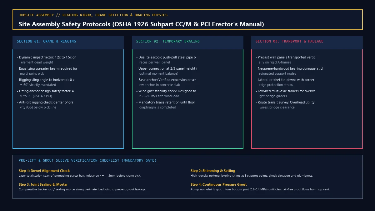
Transport and site erection represent the most safety-critical phases of the precast project. The engineering team must ensure elements are safely transported over public roads, rigged without overstress, and temporarily braced against wind storm forces.
Heavy Component Highway Transportation and A-Frame Haulage
- Trailer Selection & Securing*: Large architectural and structural wall panels must be transported vertically or near-vertically on specialized steel A-frames mounted to low-bed semi-trailers. Transporting wide wall panels horizontally exceeds legal highway clearance widths (2.55-2.60 m maximum in most jurisdictions) and induces violent out-of-plane flexural vibration cracking from road bumps.
- Bearing & Tie-Down Protection*: Wall panels rest on continuous neoprene rubber strips along the A-frame base. Heavy-duty 50 mm polyester web ratchet straps (working load limit $\ge 2,500\text{ kg}$) clamp elements against the A-frame. Polyurethane corner edge protectors prevent straps from chipping concrete corners.
- Bridge Girder & Heavy Haulage*: Transporting 30-to-40 meter prestressed concrete bridge girders weighing 80 to 120 metric tons requires multi-axle steerable hydraulic platform trailers (goldhofer type) with trailing dollies. Transport routes require engineering route surveys to verify bridge weight limits, overhead highway overpass clearances, and turning radii.
Crane Sizing, Spreader Beam Rigging and Sling Angle Physics
Jobsite crane failures occur when rigging geometry or dynamic hoisting factors are miscalculated.
- Crane Capacity Sizing & Load Radius*: The gross crane capacity must be sized for the maximum pick radius on the jobsite, accounting for the combined weight of: $$W_{gross} = W_{element} \times \text{DIF} + W_{rigging} + W_{hook}$$ where the Dynamic Impact Factor ($\text{DIF}$) is taken as 1.2 to 1.5 per OSHA 29 CFR 1926 Subpart CC and PCI Erector's Manual (MNL-127). The working hook load must not exceed 75% to 80% of the crane manufacturer’s load chart rating at that working radius.
- Rigging Sling Angle ($\theta$) Mandate*: When rigging precast members with wire rope or synthetic slings, the sling angle to the horizontal plane ($\theta$) must be maintained at $\theta \ge 60^\circ$. If the angle drops below $60^\circ$ (e.g., to $30^\circ$ or $45^\circ$), the tensile force in the sling and the compressive crushing force exerted across the concrete member escalate exponentially: $$T_{sling} = \frac{W}{n \cdot \sin(\theta)}$$ At $\theta = 30^\circ$, sling tension doubles ($1/\sin(30^\circ) = 2.0$), inducing massive horizontal compressive stresses that crush thin precast webs or shear lifting inserts.
- Equalizing Spreader Beams*: Multi-point picks (3, 4, or 8 points on long slabs or double-tees) require structural steel spreader beams with pivoting equalizing sheaves. Direct hook connection to 4 lifting points will inevitably result in only 2 diagonal slings carrying the entire load while the other 2 slings go slack, overloading the active anchors by 100%.
- Lifting Anchors Safety Factors*: Embedded lifting clutch anchors (spherical head anchors, spread anchors) must provide a minimum safety factor of 4:1 for normal handling and 5:1 for tilting and erection picks under OSHA 1926.704(b).
Site Assembly Sequence, Temporary Bracing and Wind Resistance
- Leveling and Shimming Protocol*: Wall panels and columns seat on the lower foundation or floor slab via three-point high-density plastic or steel leveling shims. Shims must possess high compressive stiffness ($f_c \ge 80\text{ MPa}$) and be set to exact laser level prior to crane hoisting. Never use more than 3 shim stacks per panel, as 4 or more stacks produce statically indeterminate rocking.
- Dual Telescopic Push-Pull Diagonal Bracing*:
- Every precast wall panel must be secured with at least two adjustable steel pipe diagonal braces immediately upon landing, prior to unhooking the crane.
- The upper brace connection must attach at approximately two-thirds ($2/3$) of the wall panel height to balance positive and negative wind bending moments.
- Base anchors must use high-strength post-installed concrete screw anchors or expanding anchors embedded into the reinforced floor slab, verified for combined shear and uplift tension.
- Wind Surcharge Safety Calculation*: Bracing systems must be engineered per ASCE 7-22 / Eurocode 1 EN 1991-1-4 to resist local peak 3-second gust wind speeds during the construction stage (typically 25 to 30 m/s). If severe gale warnings occur, mandatory supplementary tie-back cables must be secured. Braces must remain locked in place until the upper floor diaphragm is cast and fully cured.
Pressure Grouting Execution and Non-Destructive Testing (NDT) Quality Gates
Grouting rebar splice sleeves is the single most critical structural quality gate in precast construction. A hollow or partially grouted sleeve will slip under earthquake or ultimate wind loads, causing progressive structural collapse.
- Bed Joint Sealing*: Prior to grouting, the horizontal bed joint gap (20 to 30 mm shim space) under the wall panel is sealed along both exterior and interior perimeters using a non-shrink dry-pack sealing mortar or compressible closed-cell backer tape, leaving only the sleeve injection and vent tubes clear.
- Grout Mixing & Water Control*: Use pre-packaged, non-shrink, ultra-high strength cementitious grout ($f_c \ge 85-100\text{ MPa}$ at 28 days; initial expansion $0.02-2.0\%$ per ASTM C1090). Water dosage must be measured with calibrated digital scales to $\pm 1\%$ accuracy. High-speed shear mixing (1,000-1,500 rpm for 3-5 minutes) ensures complete polymer and plasticizer activation.
- Continuous Pressure Pumping*: Grout is pumped through the lower injection port using an electric screw or manual diaphragm pressure pump at 0.2 to 0.4 MPa. Pumping must proceed continuously in one direction from bottom to top, expelling all internal air.
- Visual Vent Discharge Inspection*: Grout must discharge from the upper vent tube in a steady, thick, bubble-free stream matching the consistency of the intake reservoir. Once clean grout flows, a tapered rubber plug is driven firmly into the upper vent port while maintaining pump pressure, followed immediately by sealing the lower port.
- Quality Sampling and Testing*: For every shift or 100 sleeves, sample at least 6 standard mortar test cubes (70.7 mm or 100 mm). Test compressive strength at 1 day ($\ge 35\text{ MPa}$), 3 days ($\ge 60\text{ MPa}$), and 28 days ($\ge 85-100\text{ MPa}$).
- Non-Destructive Testing (NDT) Verification: Grout sleeve fullness must be verified using Non-Destructive Testing: - Ultrasonic Pulse Velocity (UPV): Transducers placed across the sleeve measure acoustic transit time; internal voids create significant acoustic attenuation and wave delay. - Impact-Echo Testing: Acoustic resonance analysis identifies sleeve voids. - Industrial Video Endoscope*: Flexible camera probes inserted through inspection drill holes visually inspect top air vent regions for 100% sleeve grout contact.
5. Defect Diagnosis, Remediation Engineering and In-Service Maintenance
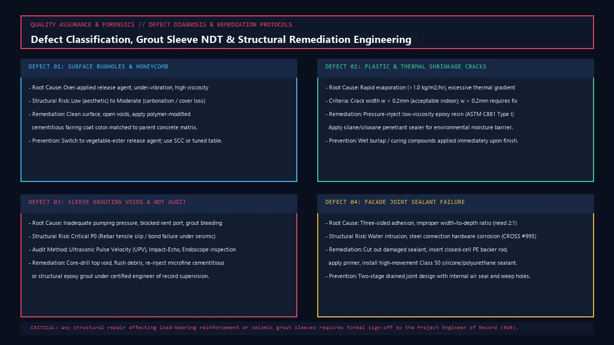
Despite rigorous factory controls, defects can occur during fabrication, handling, or service life. Project teams must apply engineering-governed diagnostic and remediation protocols.
Root-Cause Diagnostic Matrix for Common Precast Defects
| Defect Type | Primary Root Cause | Structural Severity | Standard Repair Protocol | Preventative QC Measure |
|---|---|---|---|---|
| **Surface Bugholes (Blowholes)** | Over-applied oily release agent; inadequate vibration; high concrete viscosity | Low (Aesthetic & surface carbonation risk) | Grind surface; open air pockets; apply polymer-modified cementitious fairing skim coat | Switch to pure vegetable-ester release agent; use SCC or optimize vibration amplitude |
| **Gravel Honeycombing** | Severe concrete segregation; rebar congestion blocking aggregate; mortar leakage at mold joints | High (Loss of compressive area & exposed steel) | Chip out loose aggregate to sound concrete; clean rebar; install formwork and pressure-grout structural micro-concrete | Redesign rebar clear spacing ($> 1.5 \times d_{agg}$); tighten steel mold magnetic rubber seals |
| **Plastic Shrinkage Cracks** | Rapid surface evaporation ($> 1.0\text{ kg/m}^2/\text{hr}$); dry windy factory conditions | Moderate (Durability pathway for water/chlorides) | Surface seal with silane/siloxane penetrant; epoxy injection if crack width $w > 0.2\text{ mm}$ | Apply evaporation retarder spray immediately upon screeding; wet curing blankets |
| **Demolding Edge Chipping & Spalling** | Insufficient stripping strength ($< 15\text{ MPa}$); zero draft angle on mold; rough crane hoist | Moderate (Aesthetic & cover reduction) | Saw-cut square perimeter around spall; apply bonding primer; fill with color-matched structural repair mortar | Verify maturity meter strength before stripping; ensure 2° mold draft angle |
| **Sleeve Grouting Voids** | Inadequate pumping pressure; premature plug insertion; air blockage in vent | Critical (P0 Failure: Bar pull-out slip under seismic tension) | Core-drill $\varnothing 20\text{ mm}$ hole into sleeve top void; flush debris; pressure-inject ultra-low viscosity epoxy or microfine grout | Continuous bottom-up pumping; enforce visual air-free grout overflow rule |
| **Joint Sealant Failure & Leakage** | Three-sided sealant adhesion; incorrect width-to-depth ratio; primer omitted | High (Water intrusion rusting internal connection bolts) | Cut out old sealant; insert closed-cell PE backer rod (depth = half width); apply primer; pump Class 50 silicone | Design two-stage drained joint with internal air baffle and external rainscreen seal |
Structural Crack Repair and Pressure Resin Injection Protocols
Cracks in precast concrete must be evaluated under ACI 224.1R (Causes, Evaluation, and Repair of Cracks in Concrete Structures) based on width, structural activity, and environmental exposure:
- Tolerable Crack Width Criteria*: Under ACI 224R Table 4.1, allowable crack widths under service loads are:
- Dry interior environments: $w \le 0.40\text{ mm}$ (0.016 in)
- Humid, moist exterior air: $w \le 0.30\text{ mm}$ (0.012 in)
- Deicing chemical exposure: $w \le 0.18\text{ mm}$ (0.007 in)
- Seawater / marine splash zone: $w \le 0.15\text{ mm}$ (0.006 in)
- Pressure Epoxy Injection Workflow (for Inactive Cracks $w \ge 0.20\text{ mm}$): 1. Surface Preparation: Clean concrete along the crack line using wire brushes and oil-free compressed air. 2. Port Setting: Bond surface injection ports directly over the crack at intervals equal to the member thickness (typically 150 to 300 mm spacing) using rapid-set epoxy paste. 3. Surface Capping: Seal the entire exposed crack surface between ports with epoxy paste to prevent resin escape during pressurized pumping. 4. Two-Component Resin Injection: Pump low-viscosity structural epoxy resin (conforming to [ASTM C881](https://www.astm.org/c0881_c0881m-20.html) Type I/IV Grade 1, viscosity $< 200\text{ cps}$) starting from the lowest port. Pumping continues at 0.2 to 0.5 MPa until clean resin flows from the adjacent higher port. Cap the current port and move the injection nozzle up sequentially. 5. Core Verification*: Extract $\varnothing 50\text{ mm}$ core samples across the repaired crack plane to verify $\ge 90\%$ resin penetration depth and tensile bond strength exceeding the parent concrete tensile capacity.
Facade Movement Joint Rehabilitation and Two-Stage Weatherproofing
Precast concrete facade joints endure severe seasonal thermal expansion, building drift, and driving rain:
- Root Cause of Sealant Failure*: Most joint leaks result from applying sealant directly against the back of the joint, causing three-sided adhesion. When the joint moves thermally, three-sided adhesion induces severe triaxial tearing stresses that rupture the sealant.
- Two-Stage Drained Joint Principle: Modern high-performance facades utilize a two-stage joint design: 1. Outer Rain Barrier: Deflects 90% of driving wind-rain. An open drainage cavity behind the outer seal vents water downward through weep holes. 2. Inner Airtight Seal*: Forms the primary thermal and air barrier.
- Joint Dimensioning Rule*: The joint width must be engineered based on thermal coefficient ($\alpha \approx 10 \times 10^{-6}/\text{°C}$), panel length, and sealant movement capability (Class 25 or Class 50 per ASTM C920). The sealant depth-to-width ratio must be maintained at:
- For joint widths 6 mm to 12 mm: depth = width
- For joint widths $> 12\text{ mm}$: depth = width / 2
- Closed-cell polyethylene backer rods must be compressed 25% into the joint to establish this 2:1 ratio and prevent three-sided adhesion.
6. Cross-Disciplinary Stakeholder Coordination and Conflict Resolution Playbook
A precast project’s success depends on aligning incentives across five distinct stakeholder roles who frequently operate with conflicting priorities.
``` [ STRUCTURAL DETAILER ] <=======> [ PLANT DIRECTOR ] ^ ^
| BIM / Unitechnik CAM Data | Mold Turnover & Curing
| Tolerances & Reinforcement | Batching & QC Testing v v [ GENERAL CONTRACTOR ] <========> [ RESIDENT INSPECTOR ] ^ ^
| Site Rigging & Crane Chart | Cube Strength & NDT
| Temporary Push-Pull Braces | Grout Fullness & Plumb v v [ EQUIPMENT & HARDWARE VENDOR ] (Molds, Sleeves, PCE, Magnets) ```
Multi-Role Friction Points and Real-World Disputes
- Plant Director vs. Structural Detailer: - Friction: The detailer models tight rebar cages with triple-hook bends and zero tolerance around grout sleeves, ignoring aggregate flow. The plant director experiences honeycomb voids and cannot strip panels without chipping thin corbels lacking demolding draft angles. - Resolution Protocol*: Mandatory Stage 2 Constructability Review before shop drawing sign-off. The detailer must incorporate minimum 2° draft angles on all rebar blockouts and verify clear rebar spacing $\ge 1.5 \times d_{agg}$.
- General Contractor Project Manager vs. Plant Director: - Friction: The general contractor demands just-in-time site deliveries on a congested urban jobsite with zero laydown space. The plant director needs steady production runs of identical elements to amortize mold setup costs. - Resolution Protocol*: Contractually define maximum buffer storage in the precaster's yard (minimum 2 to 3 floors of advance production). The general contractor issues binding delivery pull orders 72 hours prior to highway transport dispatch.
- General Contractor vs. Resident Inspector: - Friction: The general contractor wants to release crane hooks immediately and remove temporary diagonal wall braces within 24 hours to accelerate the schedule. The inspector refuses until 7-day grout cube test results arrive from the testing laboratory. - Resolution Protocol*: Establish staged release criteria. Crane hook unhooking is permitted immediately upon securing dual push-pull diagonal braces and shims. Diagonal brace removal is strictly locked until field-cured grout sleeve cubes reach $\ge 35\text{ MPa}$ compressive strength and the upper floor diaphragm is completed.
- Plant Director vs. Equipment / Material Supplier: - Friction: PCE admixture dosage causes unexpected slump loss during summer heat, or imported magnetic shuttering boxes lose holding force due to fine concrete dust accumulation. - Resolution Protocol*: Implement incoming raw material batch testing (slump-flow retention test on every tanker; pull-off tensile testing on magnetic boxes every 6 months).
Cross-Disciplinary Responsibility and Payment Trigger Matrix
| Lifecycle Milestone | Responsible Primary Stakeholder | Verifiable Approval Gate Document | Payment / Commercial Release Trigger |
|---|---|---|---|
| **LOD 400 BIM Freeze** | Structural Detailer & Precaster | Clash-free IFC4 / Unitechnik data package | Milestone 1: 10% Advance Mobilization |
| **Mold & Tooling Sign-off** | Equipment Vendor & Plant Director | 3D Laser dimensional scan report ($\pm 1.5\text{ mm}$) | Milestone 2: 20% Tooling Reimbursement |
| **Factory Prototype Mockup** | Plant Director & Resident Inspector | First-piece complete visual & dimensional inspection | Milestone 3: Mass Production Release |
| **Factory Batch Clearance** | Plant QC Director | 28-day concrete cube breaks; RFID yard tag | Milestone 4: 30% Factory Progress Payment |
| **Site Delivery & Receiving** | GC Logistics Lead & Truck Driver | Delivery ticket signed; zero transit damage | Milestone 5: 20% Transit Receipt |
| **Grouting & Structural Sign-off** | GC Erection Lead & Resident Inspector | Sleeve NDT report; grout cube breaks ($\ge 85\text{ MPa}$) | Milestone 6: Final 20% Release (Less Retention) |
7. What to Submit for Comprehensive Project Evaluation
When planning a new precast concrete manufacturing facility, transitioning a building project from cast-in-place to prefabricated systems, or resolving an active site installation clash, project teams should prepare a structured technical evaluation package:
- Architectural and Structural Schematic Drawings*: Floor plans, typical structural sections, column grid spacing, floor-to-floor heights, and specified lateral load resisting systems.
- Site Logistics and Geotechnical Parameters*: Soil boring logs, design water table elevations, seismic site classification, jobsite footprint boundaries, crane access paths, and road transport route limitations.
- Local Regulatory and Statutory Precast Quotas*: Jurisdictional assembly rate mandates (e.g., CIDB IBS score, Singapore BCA PPVC requirements, local green building subsidies).
- Raw Material and Production Boundary Assumptions*: Regional cement types, aggregate mineralogy, available factory footprint, and proposed line typology (carousel circulation vs. long-line prestressed beds).
For assistance structuring project inquiries, evaluating connection constructability, or organizing independent technical submittals, submit this package to the PRECAST.WORLD Technical Desk. State whether the request involves early feasibility planning, factory layout optimization, structural connection review, or active site forensic troubleshooting. That context ensures specific engineering analysis while keeping formal acceptance with the licensed project engineer of record.