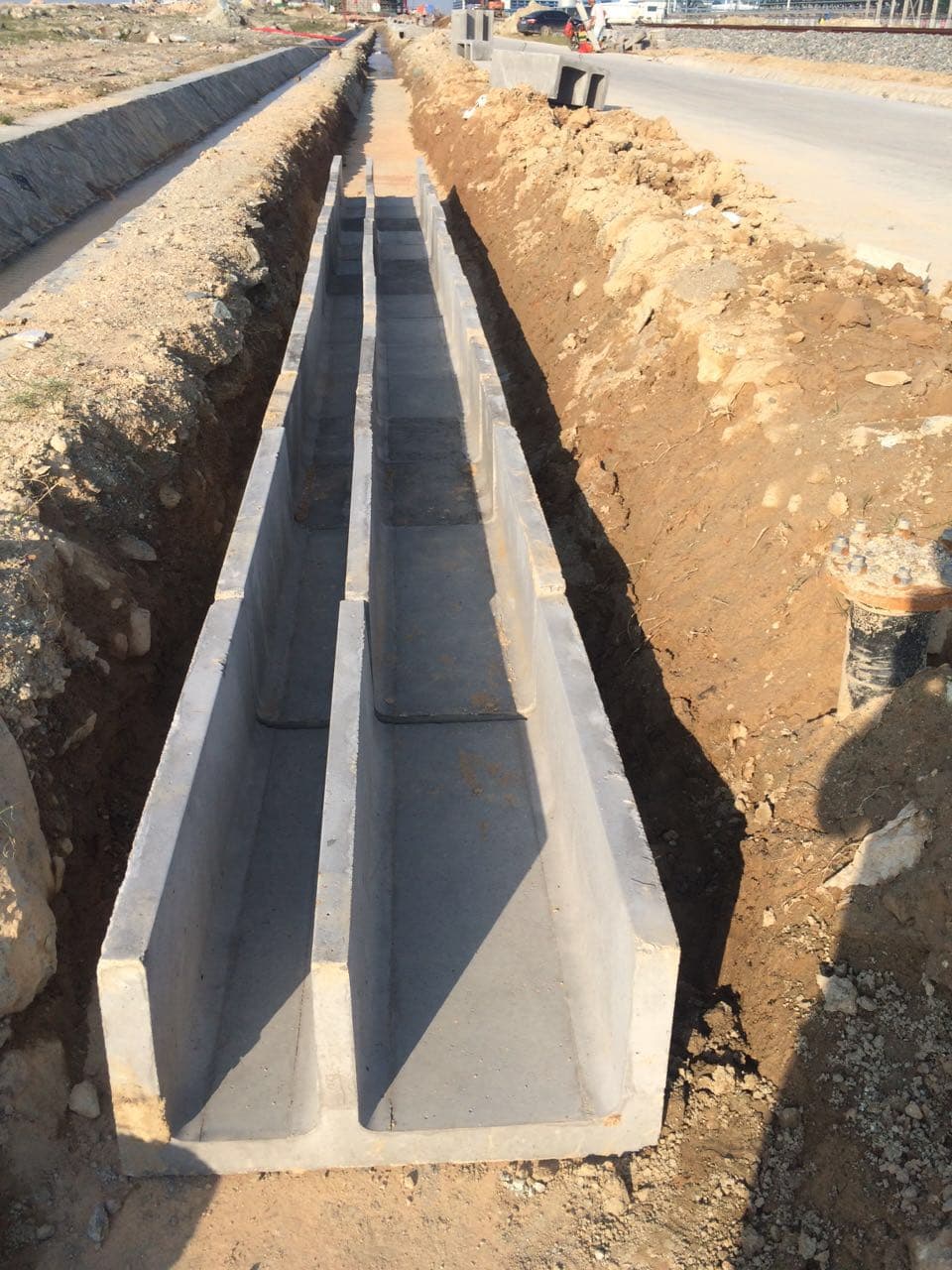
Finished precast product
Precast Concrete Cable Troughs and Covers
Modular concrete channels and removable covers that route, segregate, drain and protect power, signalling and communication cables along rail and infrastructure corridors.
A cable-trough system is defined by its route section, cable segregation, drainage, joint geometry, cover support and imposed loads. The governing authority drawings and project specification control the final module and cover details.
The system combines precast channel modules, joints, drainage or cable outlets, optional partitions and removable covers. Conventional reinforced concrete is common for the trough body; thin reactive-powder-concrete or other approved cover systems may be used where the project requires lower cover weight with defined structural performance.
- Railway subgrades and trackside service corridors
- Railway bridges, stations and depots
- Metro, light-rail and intercity rail routes
- Power, communications and industrial utility corridors
- Clear internal section and compartment arrangement
- Module length, wall thickness, end geometry and joint gap
- Cover clear span, bearing length, thickness and design load
- Concrete class, reinforcement, cover and durability exposure
Product photographs
Product form, interfaces and production context
The views below show the product itself together with relevant handling, installation or production interfaces.
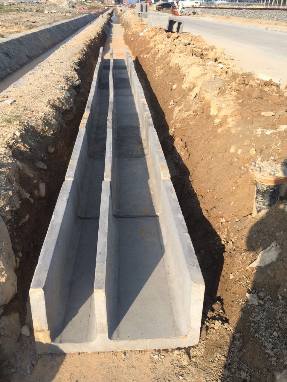
Primary product view
Modular concrete channels and removable covers that route, segregate, drain and protect power, signalling and communication cables along rail and infrastructure corridors.
Overall product view showing the form and principal interfaces.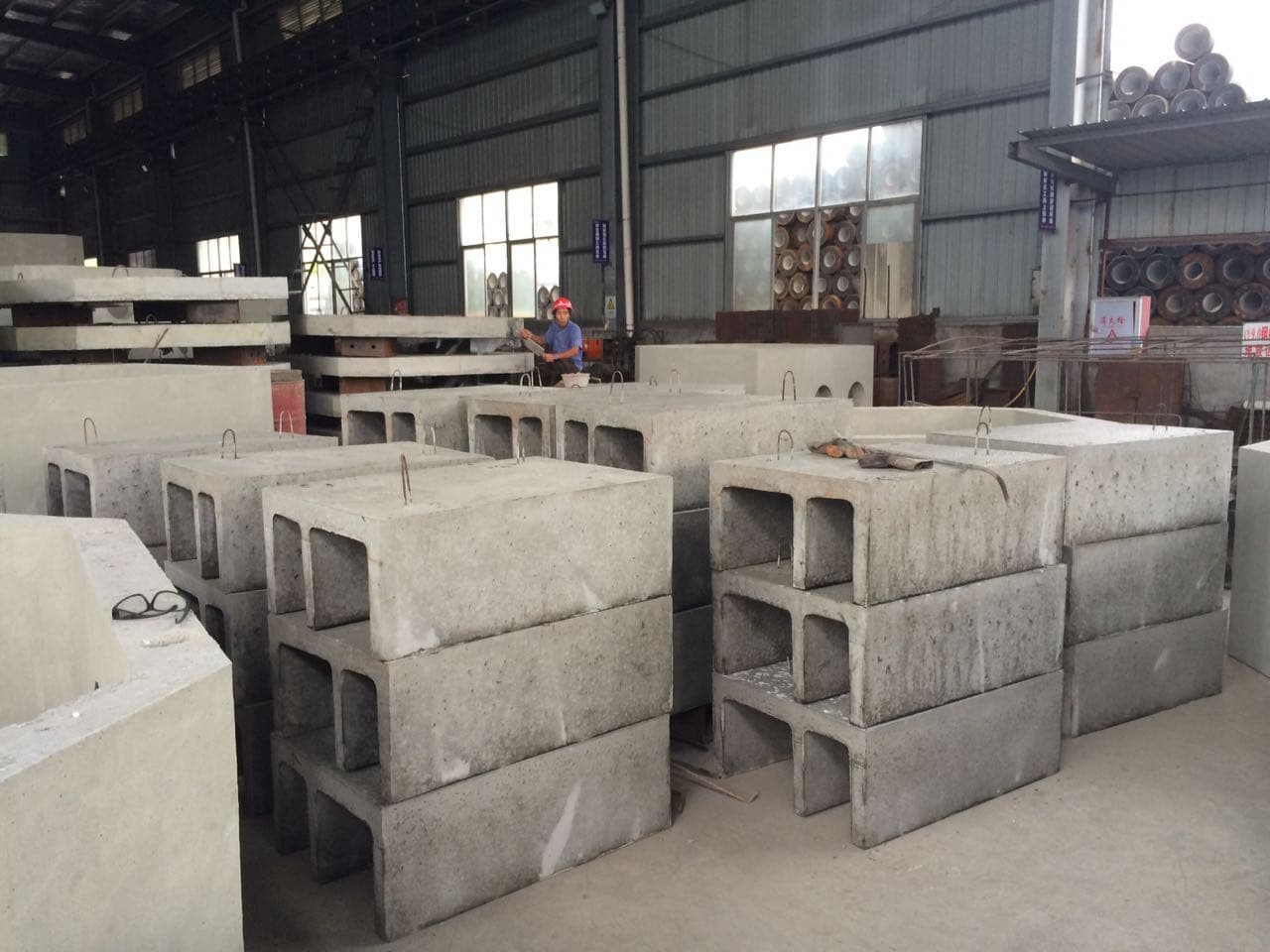
Finished channel modules
Stored modules show the open channel section, wall geometry and compartment forms that must remain consistent through production and handling.
Storage support, edge protection, markings and module orientation should preserve both geometry and route traceability before delivery.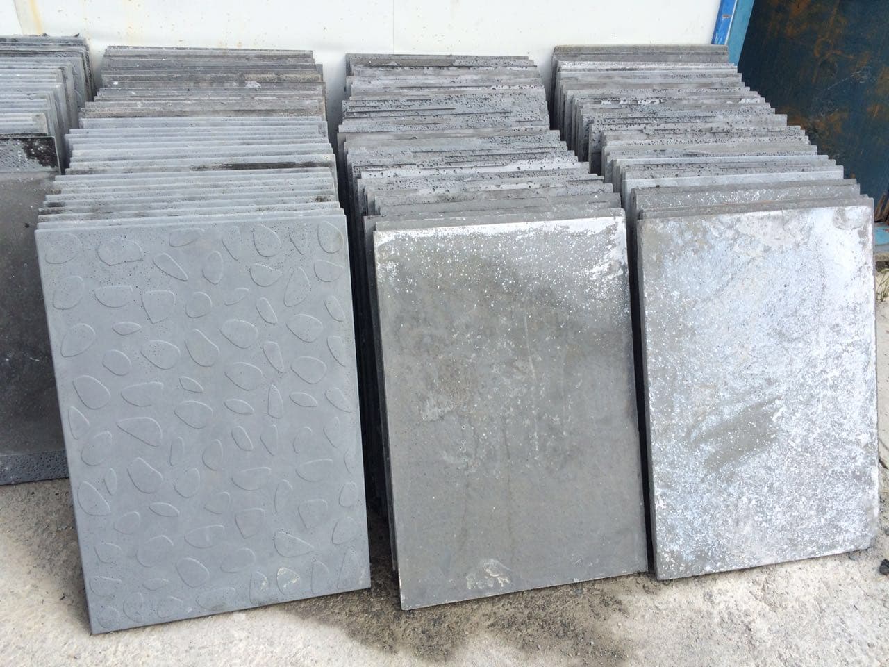
Thin RPC cover products
Thin covers use a project-defined material and structural model; surface texture and bearing geometry remain visible product interfaces.
Cover thickness alone does not define capacity. Clear span, support width, reinforcement or fibers, curing, loading method and acceptance criteria form one system.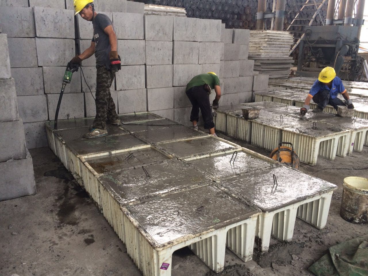
Finishing and curing stage
Surface finishing occurs while the modules remain supported by their molds, before curing, demolding and dimensional inspection.
The visible station links placement, compaction, edge formation, surface finishing and curing preparation; it is not evidence of a universal mix or cycle.Process references
Official railway-administration notice confirming amendments to the current railway subgrade construction-quality acceptance standard.
Open process referenceState Administration for Market Regulation of ChinaGB/T 31387-2015 official standard recordOfficial record confirming that the reactive-powder-concrete material standard remains current.
Open process referenceState Administration for Market Regulation of ChinaGB/T 27794-2023 official standard recordOfficial record for precast concrete electric-cable conduits; scope must be checked before applying it to an open trough-and-cover system.
Open process referenceApollo Afinitas TechnologiesConcrete pipe machines and productionOfficial joint-venture manufacturer reference for concrete pipe, manhole, box-culvert, mold, cage-welding and curing equipment scope.
Open process referenceApollo Afinitas TechnologiesCAP concrete pipe making machinesSpecific manufacturer reference for vertical vibration, reinforced and non-reinforced pipes, jacking pipes, box culverts, U-drains, manhole risers and station options.
Open process referenceTechnical references
Standards context for Precast Concrete Cable Troughs and Covers
These references identify where a technical review often starts. They are not a declaration of compliance, product approval or a replacement for the adopted project code.
Standard for Acceptance of Construction Quality of Railway Earthwork
Railway subgrade construction-quality acceptance, including current amendments and the project context in which precast cable-trough components are received and installed.
Relevant to railway subgrade work in China. Product geometry and inspection remain controlled by the adopted project drawings, authority details and contract specification.View standard recordReactive Powder Concrete
Material requirements and test context for reactive powder concrete.
Relevant only when the specified cover or component uses RPC. It does not replace the product drawing, cover loading model or project acceptance requirements.View standard recordPrecast Concrete Conduits for Electric Cable
Product requirements for precast concrete conduits used for electric cable.
Use only where the supplied product falls within the standard's conduit scope. An open railway trough with removable covers may be governed by different authority drawings and project rules.View standard recordCommon Rules for Precast Concrete Products
Common precast product requirements and conformity context used with product-specific European standards.
A common reference where adopted; it is not a cable-trough product standard and does not override the governing national annex, authority detail or project specification.View standard recordField notes
Precast Concrete Cable Troughs and Covers operating variables
A cable-trough system is defined by its route section, cable segregation, drainage, joint geometry, cover support and imposed loads. The governing authority drawings and project specification control the final module and cover details.
Parameters to verify
- Clear internal section and compartment arrangement
- Module length, wall thickness, end geometry and joint gap
- Cover clear span, bearing length, thickness and design load
- Concrete class, reinforcement, cover and durability exposure
Records and inputs
- Governing authority standard, project specification and drawing revision
- Route plan, cross-sections, chainage schedule and transition details
- Cable schedule, segregation rules, bend radius and spare-capacity requirement
- Cover loading model, maintenance access and anti-slip requirement
Failure modes to watch
- Verify product type, drawing revision, cast date and module marking before installation.
- Measure internal section, wall thickness, module length, end geometry and cover bearing interfaces at defined locations.
- Inspect cracks, chips, exposed reinforcement, honeycombing, warped covers and damaged bearing edges under agreed acceptance rules.
Main types
- Single-compartment U-shaped trough modules
- Partitioned power and communication troughs
- Modules with drainage, grounding or cable-outlet interfaces
- Reinforced-concrete covers
- Thin RPC or UHPC covers with slip-resistant surfaces
- Route-specific bends, transitions, crossings and access units
Key specifications
- Clear internal section and compartment arrangement
- Module length, wall thickness, end geometry and joint gap
- Cover clear span, bearing length, thickness and design load
- Concrete class, reinforcement, cover and durability exposure
- Drainage holes, outlet openings and longitudinal fall
- Grounding terminals, cable penetrations and reserved interfaces
- Dimensional tolerances, surface finish and edge condition
- Unit mass, lifting method, stacking support and installation sequence
Technical interface matrix
Read the product through application, geometry, production interface and acceptance evidence before comparing catalog data, drawings or technical offers.
| Area | Variables to check | Evidence normally needed | Interface risk |
|---|---|---|---|
| Application fit | Railway subgrades and trackside service corridors; Railway bridges, stations and depots; Metro, light-rail and intercity rail routes | Governing authority standard, project specification and drawing revision; Route plan, cross-sections, chainage schedule and transition details | Verify product type, drawing revision, cast date and module marking before installation. |
| Type and geometry | Single-compartment U-shaped trough modules; Partitioned power and communication troughs; Modules with drainage, grounding or cable-outlet interfaces; Reinforced-concrete covers | Governing authority standard, project specification and drawing revision; Route plan, cross-sections, chainage schedule and transition details; Cable schedule, segregation rules, bend radius and spare-capacity requirement | Measure internal section, wall thickness, module length, end geometry and cover bearing interfaces at defined locations. |
| Production interface | Route cross-sections and chainage schedules establish module geometry, transitions and quantities.; Cable groups, segregation rules, bend radius and future capacity establish the clear section and partitions.; Maintenance access, accidental loads and any vehicle or pedestrian loading establish the cover structural model. | Cable schedule, segregation rules, bend radius and spare-capacity requirement; Cover loading model, maintenance access and anti-slip requirement; Drainage direction, outlet spacing, bedding and installed-level details | Inspect cracks, chips, exposed reinforcement, honeycombing, warped covers and damaged bearing edges under agreed acceptance rules. |
| Inspection and acceptance | Cover clear span, bearing length, thickness and design load; Concrete class, reinforcement, cover and durability exposure; Drainage holes, outlet openings and longitudinal fall; Grounding terminals, cable penetrations and reserved interfaces | Cover loading model, maintenance access and anti-slip requirement; Drainage direction, outlet spacing, bedding and installed-level details; Grounding terminals, penetrations, reserved holes and embedded items; Module schedule, quantities, delivery sequence and access restrictions | Confirm drainage holes, cable outlets, partitions and grounding terminals against the route schedule. |
Technical selection variables
- Route cross-sections and chainage schedules establish module geometry, transitions and quantities.
- Cable groups, segregation rules, bend radius and future capacity establish the clear section and partitions.
- Maintenance access, accidental loads and any vehicle or pedestrian loading establish the cover structural model.
- Drainage direction, bedding, outlet spacing and local rainfall establish openings and installed levels.
- Grounding, signalling and communication interfaces establish terminals, penetrations and reserved holes.
- Transport limits, crane access and installation rhythm establish module length, unit mass and handling points.
Project interfaces and failure modes
- Using one standard module where bridge, subgrade, station and crossing sections have different interfaces.
- Treating the cover as an independent slab without matching bearing ledges, clear span and installed support.
- Adding cable outlets, drainage holes or grounding terminals after production without checking reinforcement and edge distances.
- Allowing bedding or backfill to obstruct designed drainage paths or leave modules with unsupported bearing zones.
- Accepting chipped bearing edges, rocking covers or cracked modules without mapping their position and disposition.
- Stacking or lifting units at unsupported points, creating damage that appears only during installation.
Drawings and field data normally required
- Governing authority standard, project specification and drawing revision
- Route plan, cross-sections, chainage schedule and transition details
- Cable schedule, segregation rules, bend radius and spare-capacity requirement
- Cover loading model, maintenance access and anti-slip requirement
- Drainage direction, outlet spacing, bedding and installed-level details
- Grounding terminals, penetrations, reserved holes and embedded items
- Module schedule, quantities, delivery sequence and access restrictions
- Inspection, testing, marking and traceability requirements
Inspection and interface points
- Verify product type, drawing revision, cast date and module marking before installation.
- Measure internal section, wall thickness, module length, end geometry and cover bearing interfaces at defined locations.
- Inspect cracks, chips, exposed reinforcement, honeycombing, warped covers and damaged bearing edges under agreed acceptance rules.
- Confirm drainage holes, cable outlets, partitions and grounding terminals against the route schedule.
- Check cover seating for full bearing, stable support, joint clearance and the specified surface texture.
- Record lifting points, stack supports, delivery damage and installed disposition by route location.
- Check alignment, longitudinal fall, joint continuity, bedding and backfill before cable installation closes access.
- Retain material certificates, concrete or RPC test records, dimensional reports and approved nonconformance dispositions.
FAQ
Are cable-trough dimensions standardized globally?
No. Module sections, partitions, covers, outlets and joints depend on the transport authority, route section, cable schedule and adopted project drawings. A dimension from one railway should not be transferred without checking scope.
Is an RPC cover the same product as a conventional reinforced-concrete cover?
No. RPC covers can use thinner sections and different reinforcement or fiber concepts, but their bearing geometry, design span, loading method, material controls and acceptance evidence must be defined for that product.
What normally changes between bridge and subgrade trough sections?
Support condition, available envelope, drainage, cable segregation, grounding, cover access, transitions and installation sequence can all change. The route drawings should identify each section and interface.
Why must local producers be searched by location?
Trough modules are heavy, project-specific finished precast products. Transport radius, authority approval, route logistics, installation support and delivery sequence usually make local or regional production more relevant than distant export supply.
Ask the technical desk about precast concrete cable troughs and covers
Send product type, capacity target, standards, drawings, photos or quality issues. PRECAST.WORLD will turn them into clearer technical notes for the next discussion.